Joint stabilizing instrument and method of use

a stabilizing instrument and joint technology, applied in the field of variable, can solve the problems of affecting the patient's recovery, and the instrumentation used may require a lot of time,

Inactive Publication Date: 2014-01-09
STRYKER CORP
View PDF6 Cites 7 Cited by
  • Summary
  • Abstract
  • Description
  • Claims
  • Application Information

AI Technical Summary

Benefits of technology

[0009]Embodiments of the aforementioned first aspect may also include a curved portion on the first extension, such curved portion containing a first curved section and a second curved section, the first section curving in an opposite direction to the second section. Al...

Problems solved by technology

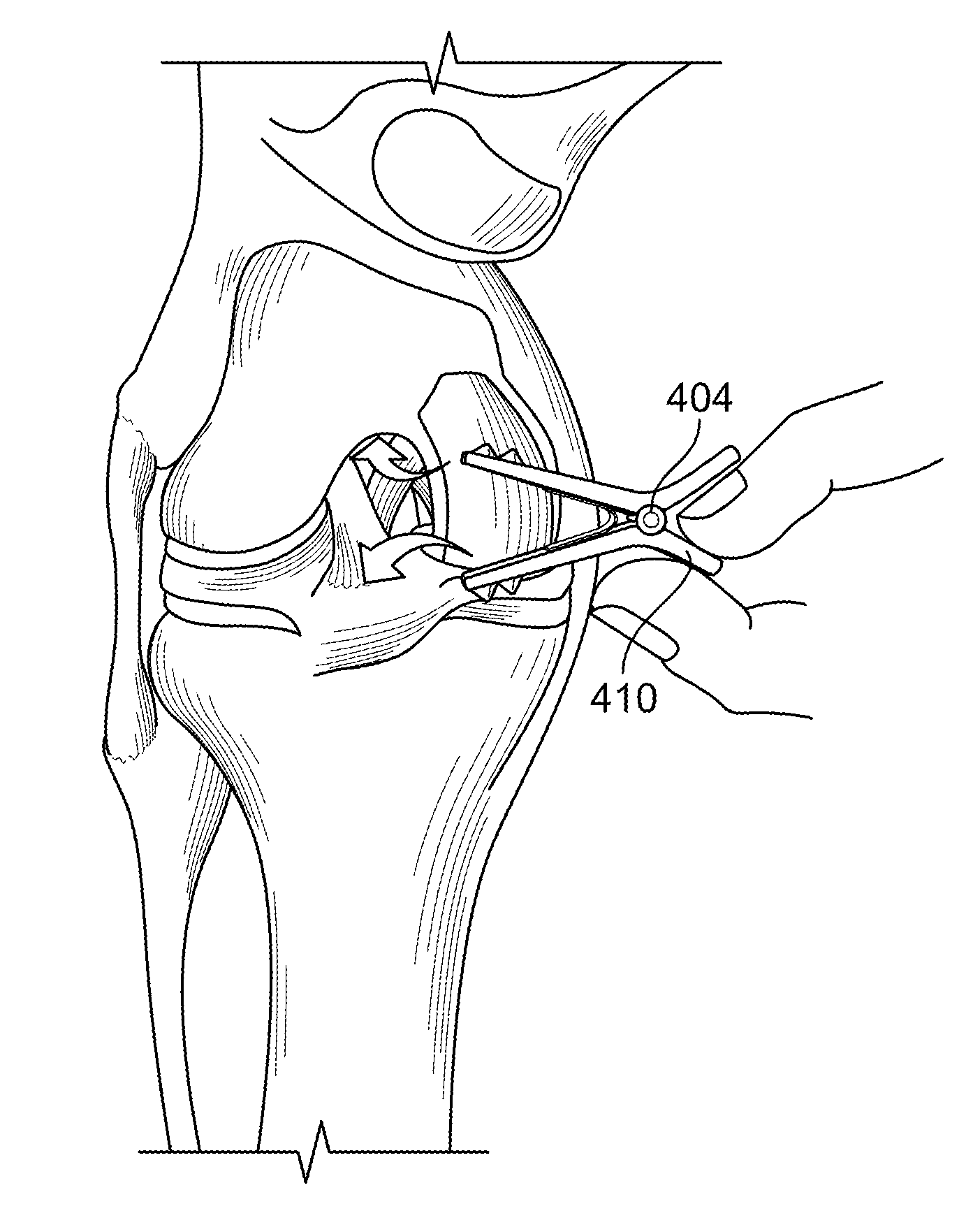
When this space is not maintained, it is possible for the bones (e.g., the tibia and the femur) to essentially collapse on the cutting tool used, which can cause a less than optimal result in bone preparation and have negative consequences for the patient.
A challenge with maintaining joint stability and relative distance between the distal femur and the proximal tibia is that the cutting instrumentation used may require a certain working volume around an opened joint capsule.
Therefore, use of a standard retraction instrument (e.g., a Gelpi retractor) for stabilizing the joint...

Method used


Image

  • Joint stabilizing instrument and method of use
  • Joint stabilizing instrument and method of use
  • Joint stabilizing instrument and method of use

Examples


Embodiment Construction

[0035]In describing the preferred embodiments of the invention(s) illustrated and to be described with respect to the drawings, specific terminology will be used for the sake of clarity. However, the invention(s) is not intended to be limited to any specific terms used herein, and it is to be understood that each specific term includes all technical equivalents, which operate in a similar manner to accomplish a similar purpose.

[0036]As used herein, the term “distal” means relatively farther from the heart and the term “proximal” means relatively closer to the heart; the term “inferior” means toward the feet and the term “superior” means towards the head; the term “anterior” means towards the forward facing part of the body (e.g., the face) and the term “posterior” means towards the back of the body; and the term “medial” means toward the midline of the body while the term “lateral” means away from the midline of the body. These terms are anatomical terms used mainly to describe the ...


PUM


Abstract

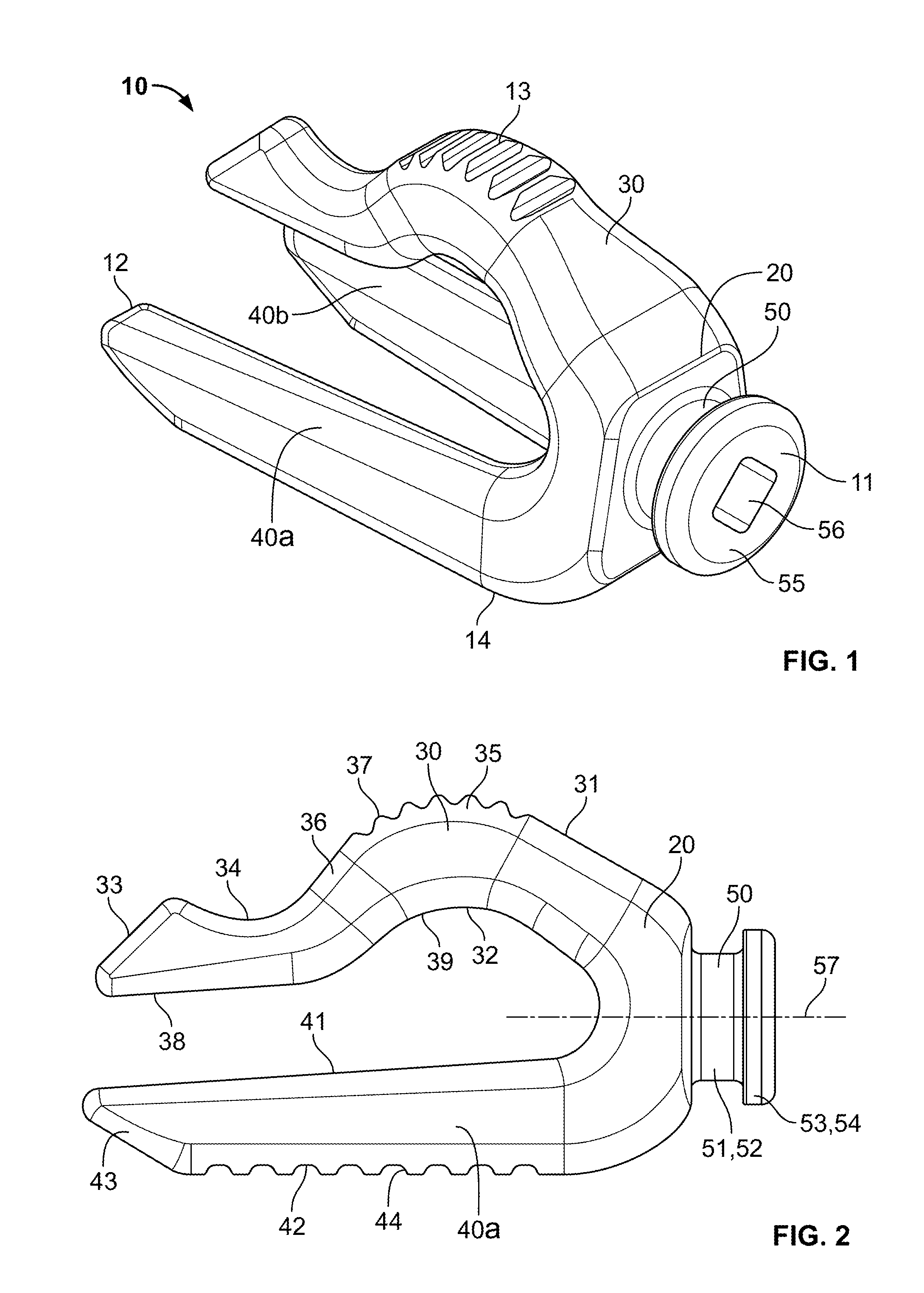
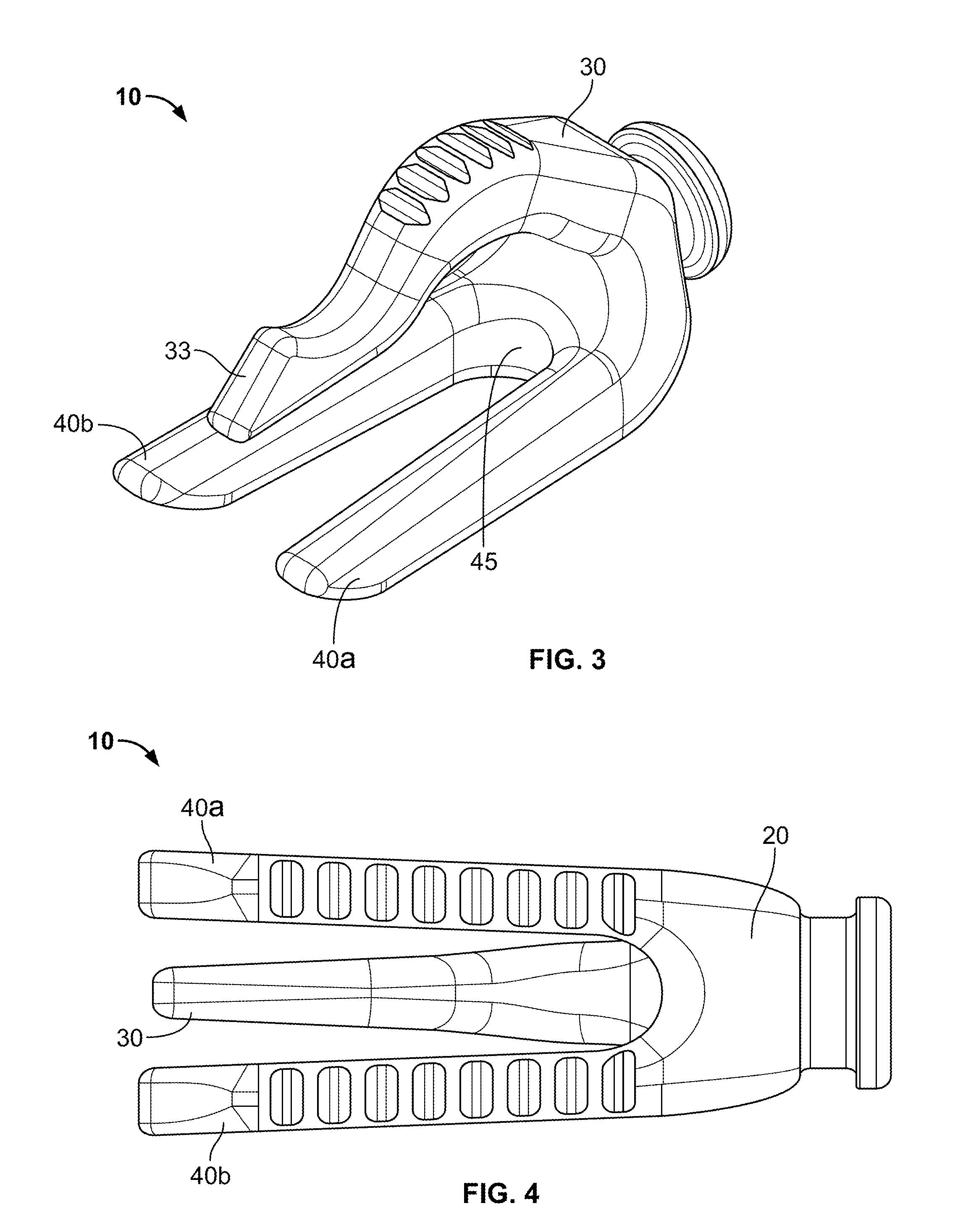
A joint spacer having a body and a series of extensions projecting therefrom is disclosed. A first of the series of extensions may include a curved section for housing a portion of a joint therein (e.g., the intercondylar notch of a knee), and a second and third of the extensions may be configured to abut an opposing portion of the joint. Once inserted, the joint spacer may maintain the spacing between, and the stabilization of, the joint during surgery. A fourth extension may be included with the spacer in which the extension may interact with an insertion-removal instrument. The insertion-removal instrument may include one end having an insertion geometry for use in inserting the spacer into the joint, and an opposing end having a removal geometry for removing the spacer. Related methods for inserting the joint spacer and various alternate joint distraction devices are also disclosed.

Description

CROSS-REFERENCE TO RELATED APPLICATIONS[0001]The present application claims the benefit of the filing date of U.S. Provisional Patent Application No. 61 / 667,583, filed Jul. 3, 2012, the disclosure of which is hereby incorporated by reference herein.BACKGROUND OF THE INVENTION[0002]The present invention(s) relates generally to various spacers and / or distraction instruments, and more particularly to spacers or distraction instruments configured to maintain the spacing between contiguous bone segments during surgery (e.g., knee surgery).[0003]In traditional knee arthroplasty surgery, the diseased bone and / or cartilage of a patient is typically removed and replaced with a prosthetic implant. An example of a prosthetic implant for use in an arthroplasty surgery is set forth in U.S. patent application Ser. No. 13 / 530,927 (the “'927 Application”), the disclosure of which is hereby incorporated by reference herein in its entirety.[0004]To accommodate a prosthetic implant, of the type disclo...

Claims


Application Information

Patent Timeline
IPC IPC(8): A61B17/02
CPCA61B17/025A61B17/0206A61B2017/0046A61B2017/00557A61B2017/0268A61B2017/2837
Inventor FOSSEZ, JOHN R.AXELSON, JR., STUART L.LAROY, TIMOTHY J.VELDKAMP, DAVE J.WORM, DUSTIN L.
Owner STRYKER CORP
Why Eureka
Try Eureka