Shock absorbing, total disc replacement prosthetic

a total disc replacement and shock absorption technology, applied in the field of shock absorption and total disc replacement prosthetics, can solve the problems of restricting spinal mobility, drastic treatments are usually unable to restore normal disc function, and devices that restrict motion in such a manner do not allow the natural motion of the vertebrae, and achieve the effect of convenient placemen

Inactive Publication Date: 2014-01-09
TRUEMOTION SPINE
View PDF22 Cites 17 Cited by
  • Summary
  • Abstract
  • Description
  • Claims
  • Application Information

AI Technical Summary

Benefits of technology

[0026]In one embodiment of a disc sled, the orifice in the bottom endplate cavity provides a tight fit for insertion. Once inserted, a cavity lip can prevent the sled and nucleus from being expelled from between the plates during nominal operation, thus, creating a profile-closed planar joint. In an alternative embodiment of a rounded-corners square sled, a separate sled retaining ring, in lieu of a cavity lip, can be fixedly or removeably attached to the bottom endplate, after the sled has been inserted in the bottom endplate cavity. In a further embodiment, the bottom end plate cavity can be made larger than the sled dimensions to easily accommodate such a placement. After fixing the sled retaining ring to the bottom endplate, there will be a retaining lip around the cavity, to retain the sled, hence the entire nucleus, between the plates, even during motion of the sled within the cavity, thus, creating a profile-closed planar joint.
[0027]In one embodiment, a viscoelastic boot in slight tension, when fixed to the endplates, separates the invention's interior space from its external environment and can provide resistance to extension forces and general torsion. Such a boot also can protect the mechanism from osteoblasts and other cell matter from fouling the mechanism during the healing process.

Problems solved by technology

The latter treatment, while providing short term relief, limits spinal mobility and often leads to excessive forces on facet joints adjacent to the fusion and may create further problems over time.
Drastic treatments are usually unable to restore normal disc function.
467-474), devices that restrict motion in such a manner do not allow the natural motion of the vertebrae, either for sagittal plane motion or for combined sagittal, lateral and axial motion.
Further, when the two plates, as described in the cited patents, are not in contact, the devices are unable to provide stability to the intervertebral interface, which can allow free motion and lead to disc related spondylolisthesis, FSU instability and excessive facet loading.
Nonetheless, motion coupling between flexion-extension, axial rotation, and lateral bending and other functional spinal units involved in the overall spinal motion, increases the complexity and difficulty in developing a prosthetic disc replacement that realizes natural spinal motion.
Producing such complex disc motions with strictly articulating joints is at best problematic.
Additional motion complexity required of a spinal disc derives from motion constraints dictated by facet joints.
Natural spinal motions, therefore, can place severe requirements on the design of a prosthetic disc, requiring a minimum of six independent degrees of freedom to fully enable complete spinal motion.
Using only mechanically articulating joints, therefore, can be problematic in resolving complex disc motion.

Method used


Image

  • Shock absorbing, total disc replacement prosthetic
  • Shock absorbing, total disc replacement prosthetic
  • Shock absorbing, total disc replacement prosthetic

Examples


Embodiment Construction

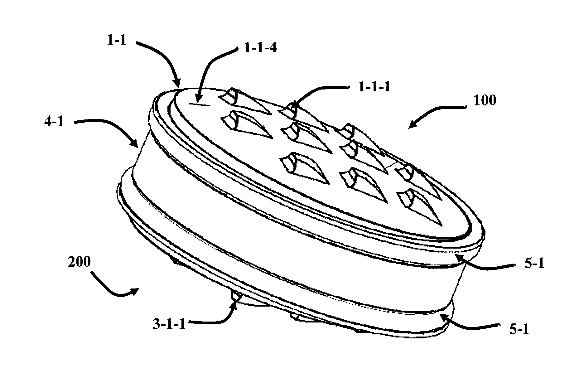
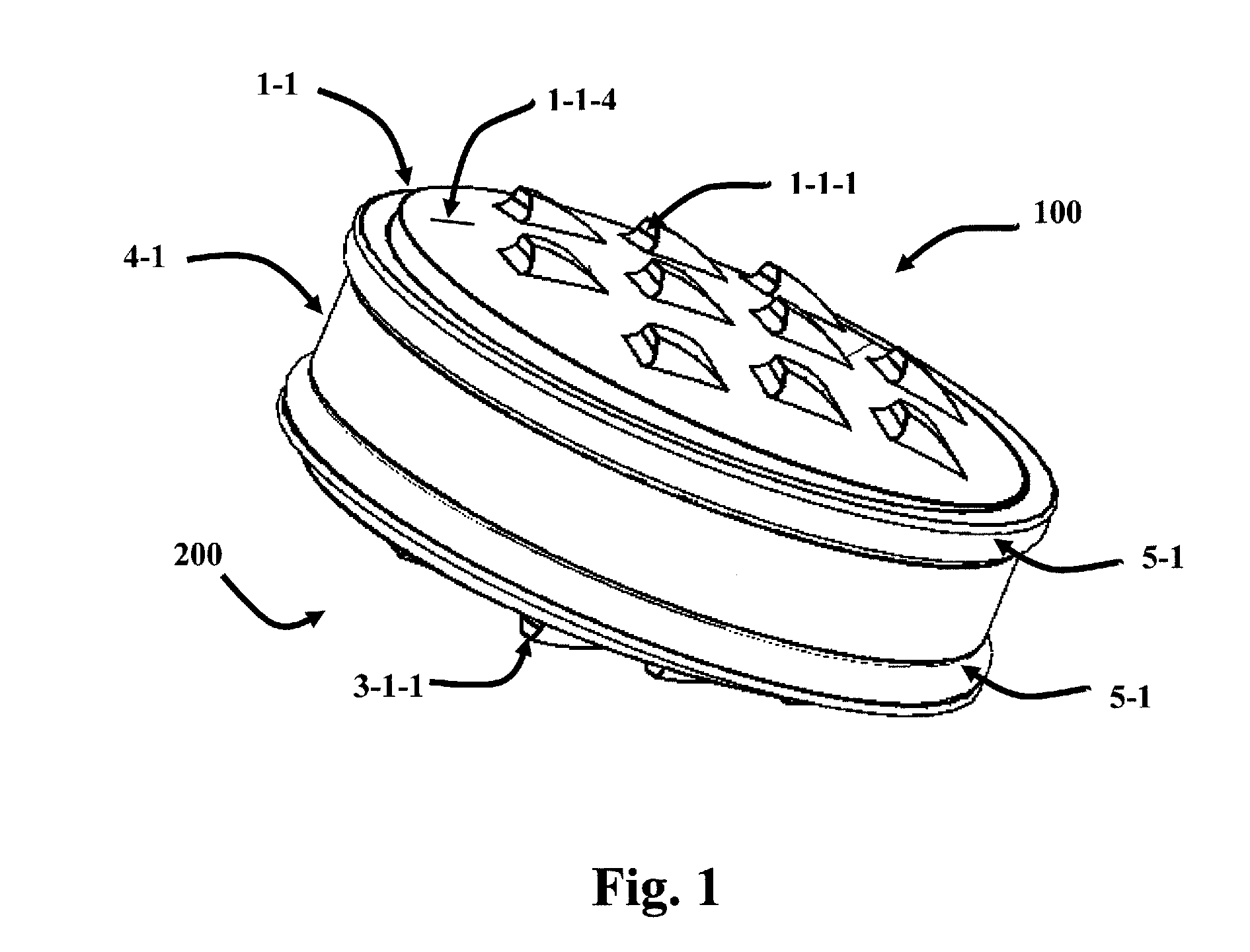
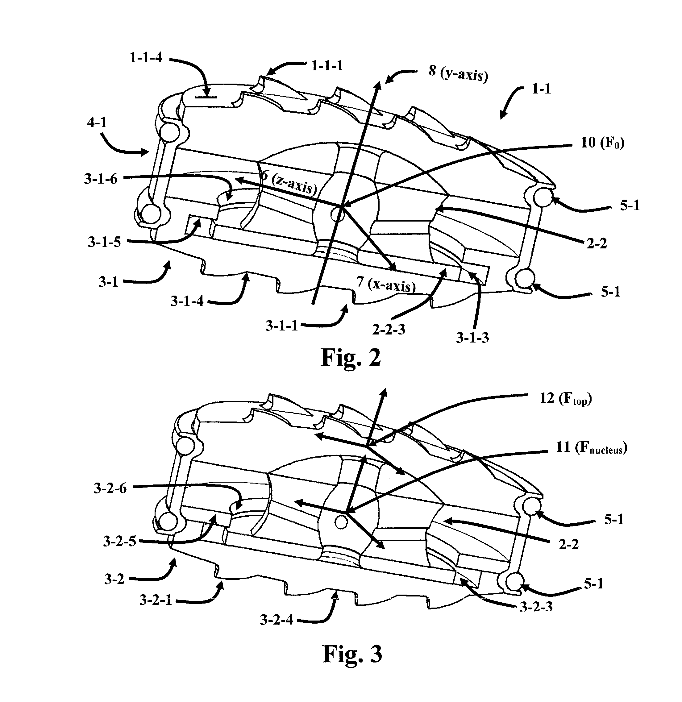
[0046]The subject invention pertains to embodiments of a device capable of providing motion with up to six independent degrees-of-freedom and redundant flexure degrees of freedom. Specifically, articulating mechanical joints of the invention can provide five independent degrees of freedom and one redundant axial rotation degree-of freedom. Flexure between the two mechanical joints provides an additional axial degree of freedom and allows a continuum of motions within the rated modulus of the material. In particular, flexure in the invention accommodates compression-extension motions along the axial axis of the FSU independent of the articulation joint degrees of freedom. Embodiments of the device can further simultaneously provide reaction to compressive, tension and torsion loads. More specifically, the subject invention pertains to embodiments of a device capable of approximating the potential motion between two vertebrae in a spine

[0047]The following description will disclose emb...


PUM

PropertyMeasurementUnit
degree of rotationaaaaaaaaaa
thicknessaaaaaaaaaa
thicknessaaaaaaaaaa

Abstract

Devices for implantation within a Functional Spinal Unit (FSU) that can provide up to six independent degrees of freedom from a neutral position are provided. Such devices can comprise two endplates, a nucleus, a sled, and an optional, elastic boot attached to the endplates and enclosing the contents of the device, namely, the nucleus. The sled on one end of the nucleus can be moveably attached to one of the endplates and a spherical cap affixed to the opposite end of the nucleus can be operably engaged with the other endplate. The endplates can provide outer surface features that allow fusion of the plates to the superior and inferior vertebrae of a FSU and can prevent expulsion of the device immediately after implanting. The nucleus can have compliant elements or can be rigid. It can comprise a tripartite construction of three elements of possibly different materials that can be fitted together, or it can be a single unified element or can be a material with graded mechanical moduli axially and radially. The endplates and nucleus can maintain connection through the sled and the extension of the central core. Additionally, one or more specialized rotational joint stops can be utilized to provide profile-closure of the spherical joint between the top endplate and the spherical cap.

Description

CROSS-REFERENCE TO RELATED APPLICATION[0001]The present application claims the benefit of U.S. Provisional Application Ser. No. 61 / 668,536, filed Jul. 6, 2012, which is hereby incorporated by reference herein in its entirety, including any figures, tables, or drawings.BACKGROUND OF INVENTION[0002]Spinal disc herniation, a common ailment, and degenerative disc disease often induce pain, as well as neurologically and physiologically debilitating consequences, for which relief becomes paramount. If conservative treatments fail, the more drastic measures of discectomies and spinal fusion may be indicated. The latter treatment, while providing short term relief, limits spinal mobility and often leads to excessive forces on facet joints adjacent to the fusion and may create further problems over time. Drastic treatments are usually unable to restore normal disc function. The loss of disc function has led to a number of disc prostheses that attempt to provide natural motion.[0003]The liter...

Claims


Application Information

Patent Timeline
Patent Type & Authority Applications(United States)
IPC IPC(8): A61F2/44
CPCA61F2/442A61F2/4425A61F2002/30006A61F2002/30224A61F2002/30235A61F2002/30299A61F2002/30309A61F2002/30364A61F2002/30365A61F2002/30372A61F2002/30495A61F2002/305A61F2002/30563A61F2002/30581A61F2002/30604A61F2002/30607A61F2002/3064A61F2002/30644A61F2002/30649A61F2002/30673A61F2002/30787A61F2002/30836A61F2002/30841A61F2002/30968A61F2002/3098A61F2002/4435A61F2310/00407B33Y80/00A61F2002/30639A61F2/3094
Inventor DOTY, KEITH, L.
Owner TRUEMOTION SPINE
Why Eureka
Try Eureka