
System and method for operating a hybrid vehicle system

a hybrid vehicle and vehicle system technology, applied in the direction of process and machine control, battery/fuel cell control arrangement, instruments, etc., can solve the problems of increasing the cost, maintenance needs and weight of the vehicle system, and the inability to add weight for some vehicle systems

Active Publication Date: 2014-01-09
GE GLOBAL SOURCING LLC
View PDF1 Cites 50 Cited by
  • Summary
  • Abstract
  • Description
  • Claims
  • Application Information

AI Technical Summary

Benefits of technology

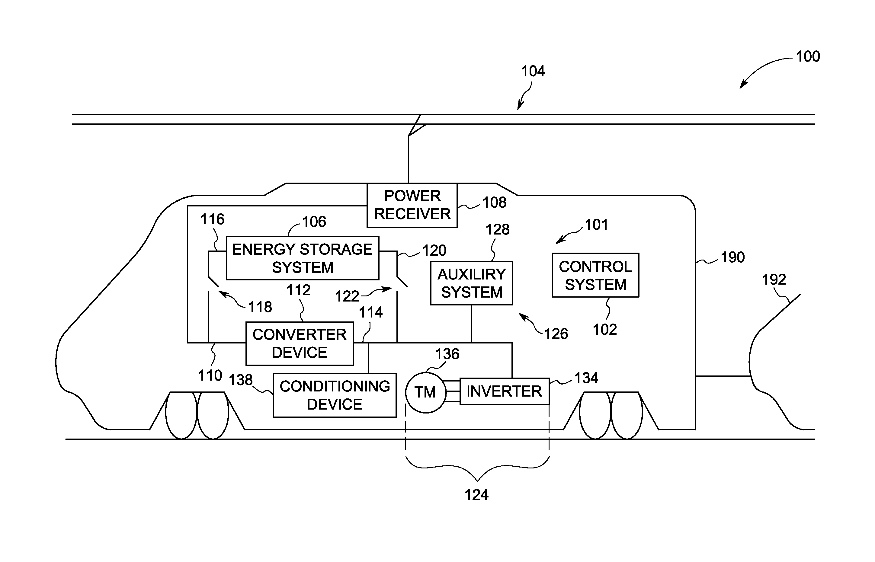
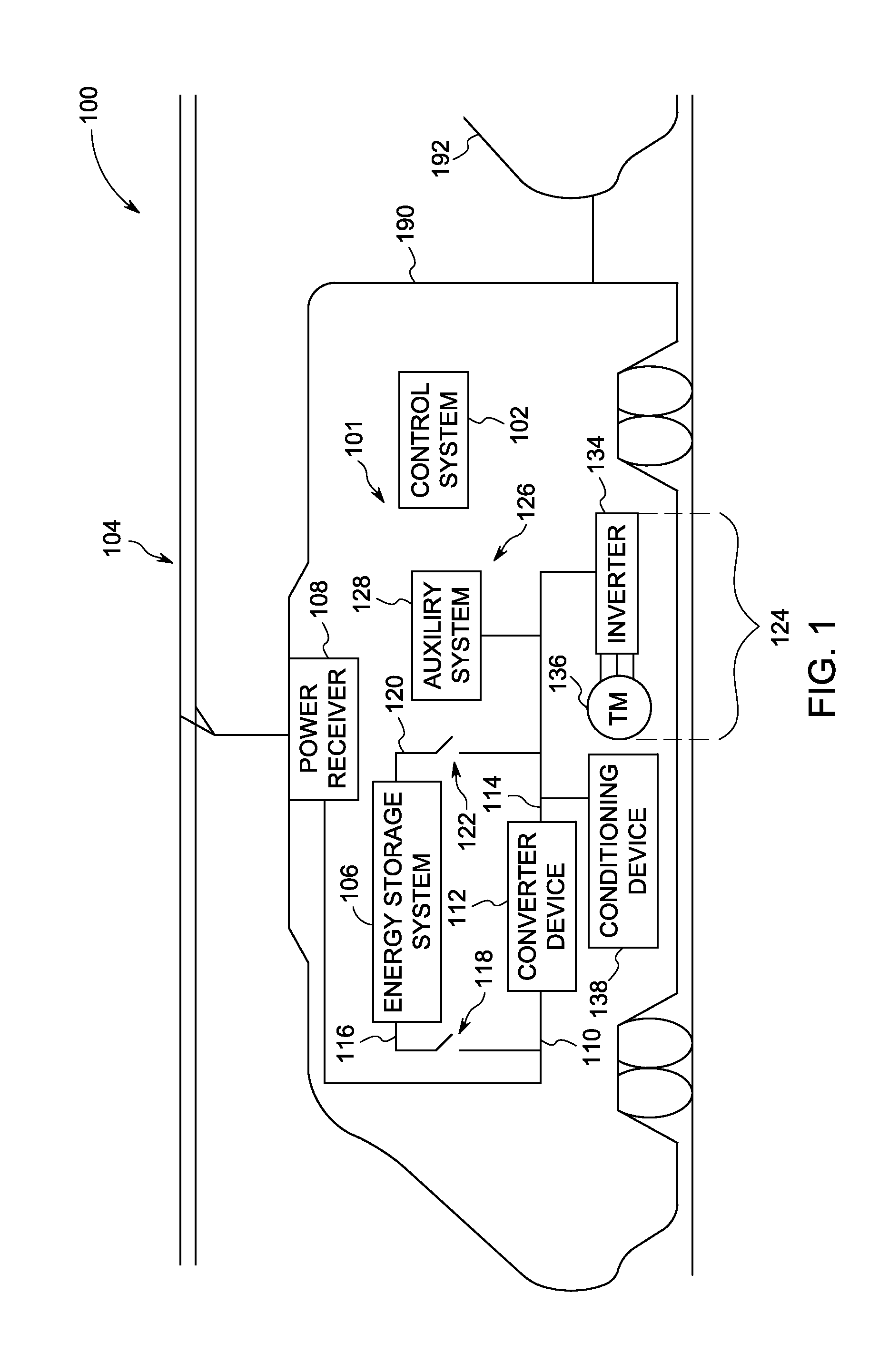
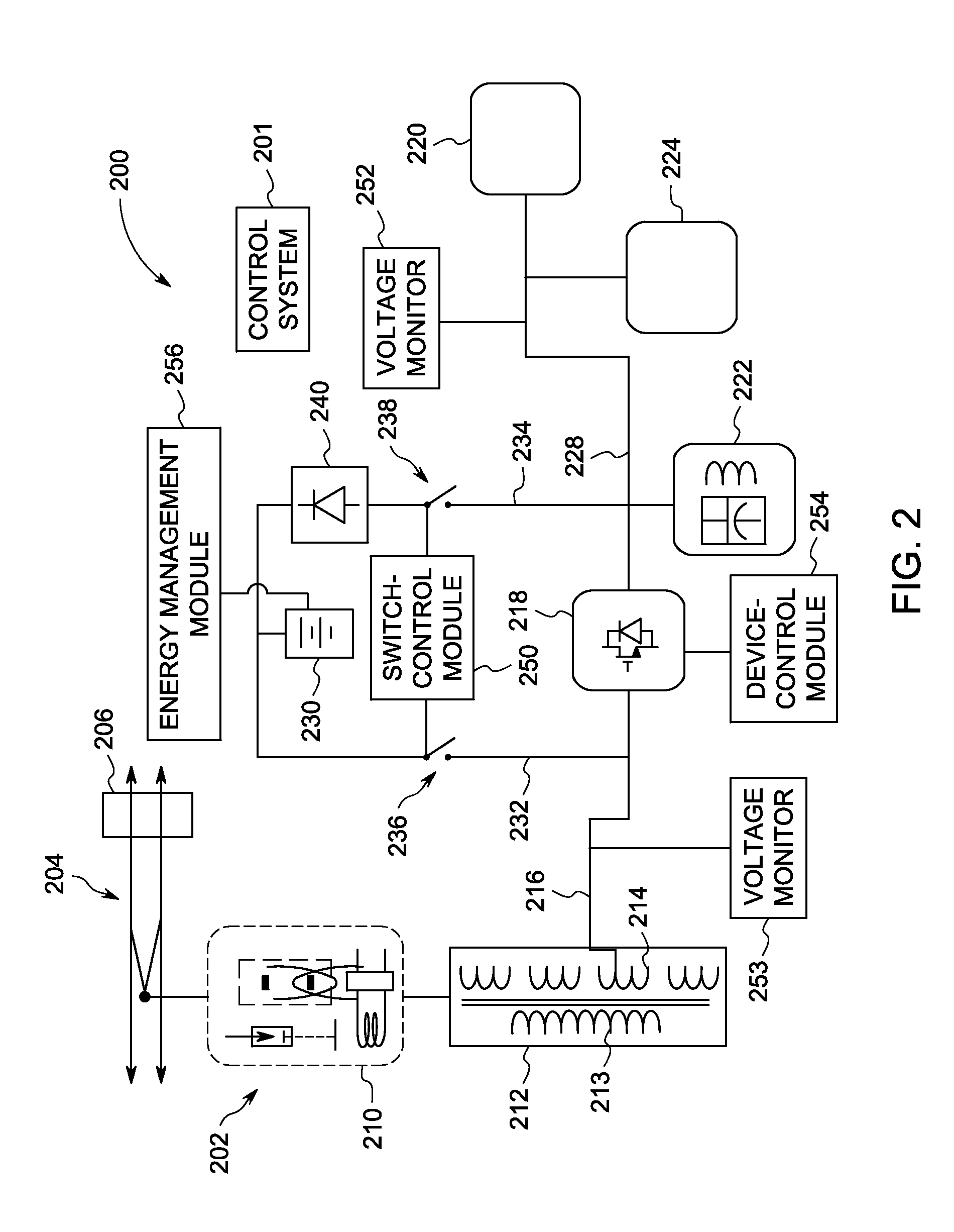
The patent describes a system for powering a vehicle system using an external power source and an energy storage system. The system includes a switch control module that controls the operation of contactors which connect the energy storage system to the front-end and direct-current (DC) buses. The converter device converts the electrical power from the external power source to DC power and supplies it to the DC bus. The energy storage system is charged when the vehicle system is connected to the external power source, while the propulsion system is powered when the vehicle system is decoupled from the external power source. The system also includes an energy storage system that can operate in a charging mode and a supply mode, allowing for efficient charging and powering of the propulsion system without the need for a voltage converter. The technical effects of this system include improved efficiency and flexibility in powering a vehicle system.

Problems solved by technology

The external power source, however, may not be accessible for the entire route.
These additional intermediate components, however, can significantly increase the cost, maintenance needs, and weight of the vehicle system.
Such an addition of weight may not be possible for some vehicle systems (e.g., automobiles), and may be undesirable for other vehicle systems.
With respect to locomotives, adding one or more transformers can significantly increase the weight of the locomotive and thereby require additional tractive effort to propel the locomotive.
In addition, transformers can consume additional volume in the limited space of a vehicle system.

Method used


Image

  • System and method for operating a hybrid vehicle system
  • System and method for operating a hybrid vehicle system
  • System and method for operating a hybrid vehicle system

Examples


Embodiment Construction

[0016]One or more embodiments of the inventive subject matter described herein provide systems and methods for powering a vehicle system with different types of power sources (e.g., a hybrid vehicle system). For various embodiments, at least one of the power sources is an energy storage system that is carried by the vehicle system. In particular embodiments, the vehicle system is capable of being powered by an external power source (e.g., catenary or overhead lines, third rail, and the like). The vehicle system may travel along a designated route that includes, for at least some portions of the route, the external power source extending therealong. The vehicle system may be operably coupled to the external power source for a first portion of the route such that the external power source supplies electrical power to the vehicle system. During a second portion of the route, however, the vehicle system may not be operably connected to the external power source. A vehicle system may not...


PUM


Abstract

System including a switch control module that is configured to control operation of a first contactor and a second contactor in a vehicle system. The first and second contactors are configured to selectively connect front-end and direct-current (DC) buses, respectively, to an energy storage system of the vehicle system. The front-end bus is configured to receive electrical power from an external power source and provide the electrical power to a converter device. The converter device is configured to supply DC power to the DC bus. The switch control module is configured to close the second contactor when the vehicle system is operably coupled to the external power source so that the energy storage system is charged by the DC power. The switch control module is configured to close one of the first contactor or the second contactor when the vehicle system is operably decoupled to the external power source.

Description

[0001]This application claims the benefit of U.S. Provisional Application Nos. 61 / 784,482 (“the '482 Application”), which was filed on 14 Mar. 2013, 61 / 668,432 (“the '432 Application”), which was filed on 5 Jul. 2012, and 61 / 722,744 (“the '744 Application”), which was filed on 5 Nov. 2012. Each of the '482, '432, and '744 Applications is incorporated herein by reference in its entirety.BACKGROUND[0002]Known vehicle systems (e.g., locomotives, automobiles, mining equipment, etc.) may include traction motors that provide tractive efforts to propel the vehicle systems. In some cases, the traction motors may be powered by more than one power source. For example, existing hybrid vehicles may be powered by diesel-driven generators and also by on-board energy storage systems (e.g., battery systems). In other cases, a hybrid vehicle system may be powered by the energy storage system and an external power source, such as overhead lines or third rail. The external power source, however, may n...

Claims


Application Information

Patent Timeline
Patent Type & Authority Applications(United States)
IPC IPC(8): B60W20/00B60W10/08B60W10/30B60L11/18
CPCB60W20/00B60L11/1809B60W10/08B60W10/30Y10S903/93B60L1/00B60L2240/547B60L3/0023B60L9/18B60L9/24Y02T90/14B60L2200/26Y02T10/7072B60L50/53B60L53/00B60L58/19B60L58/22B60L58/20B60L50/66Y02T10/70
Inventor KUMAR, AJITH KUTTANNAIRDAUM, WOLFGANGIOANNIDIS, DIMITRIOS
Owner GE GLOBAL SOURCING LLC
Learn More