Thermoelectric temperature control unit

Inactive Publication Date: 2014-01-16
MAHLE INT GMBH
View PDF13 Cites 24 Cited by
  • Summary
  • Abstract
  • Description
  • Claims
  • Application Information

AI Technical Summary

Benefits of technology

[0037]This alternate arrangement of the flow ducts results in an advantageous distribution pattern, especially as regards temperature distribution over the first and second flow ducts.
[0038]It is furthermore advantageous if the thermoelectric temper

Problems solved by technology

In this regard, however, there are no known solutions suitable for series production at present that provide sufficient cooling and heating capacity with an appropriate installation space requirement.
The disadvantage with the prior art is, in parti

Method used


Image

  • Thermoelectric temperature control unit
  • Thermoelectric temperature control unit
  • Thermoelectric temperature control unit

Examples


Embodiment Construction

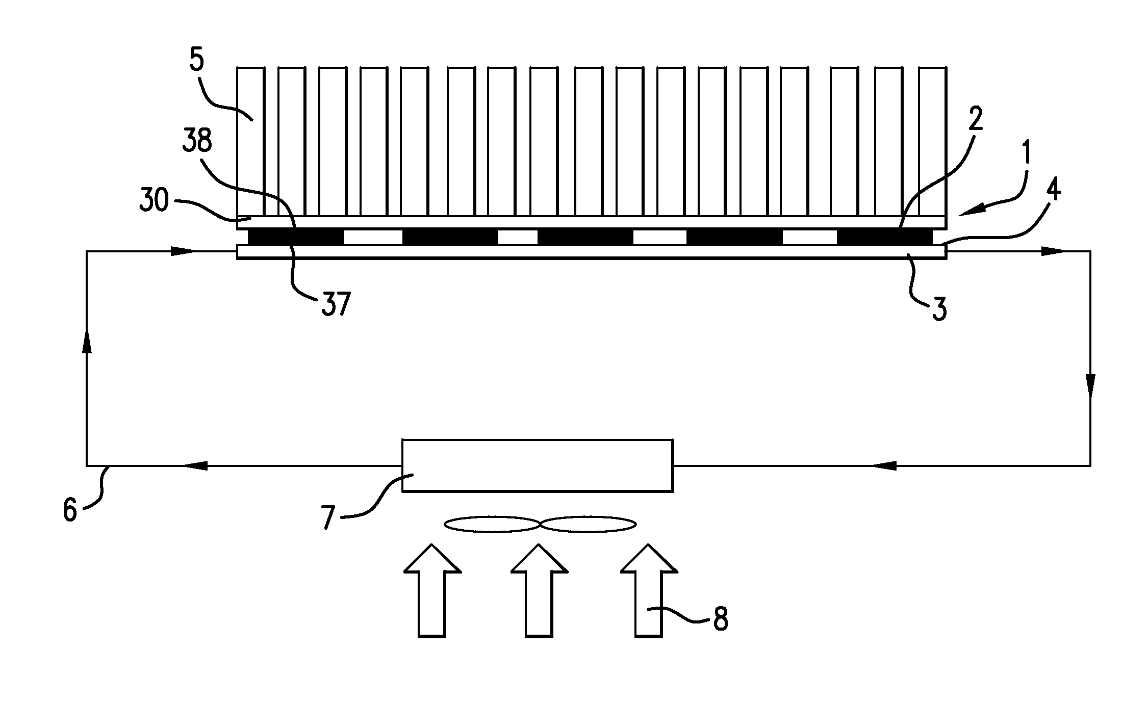
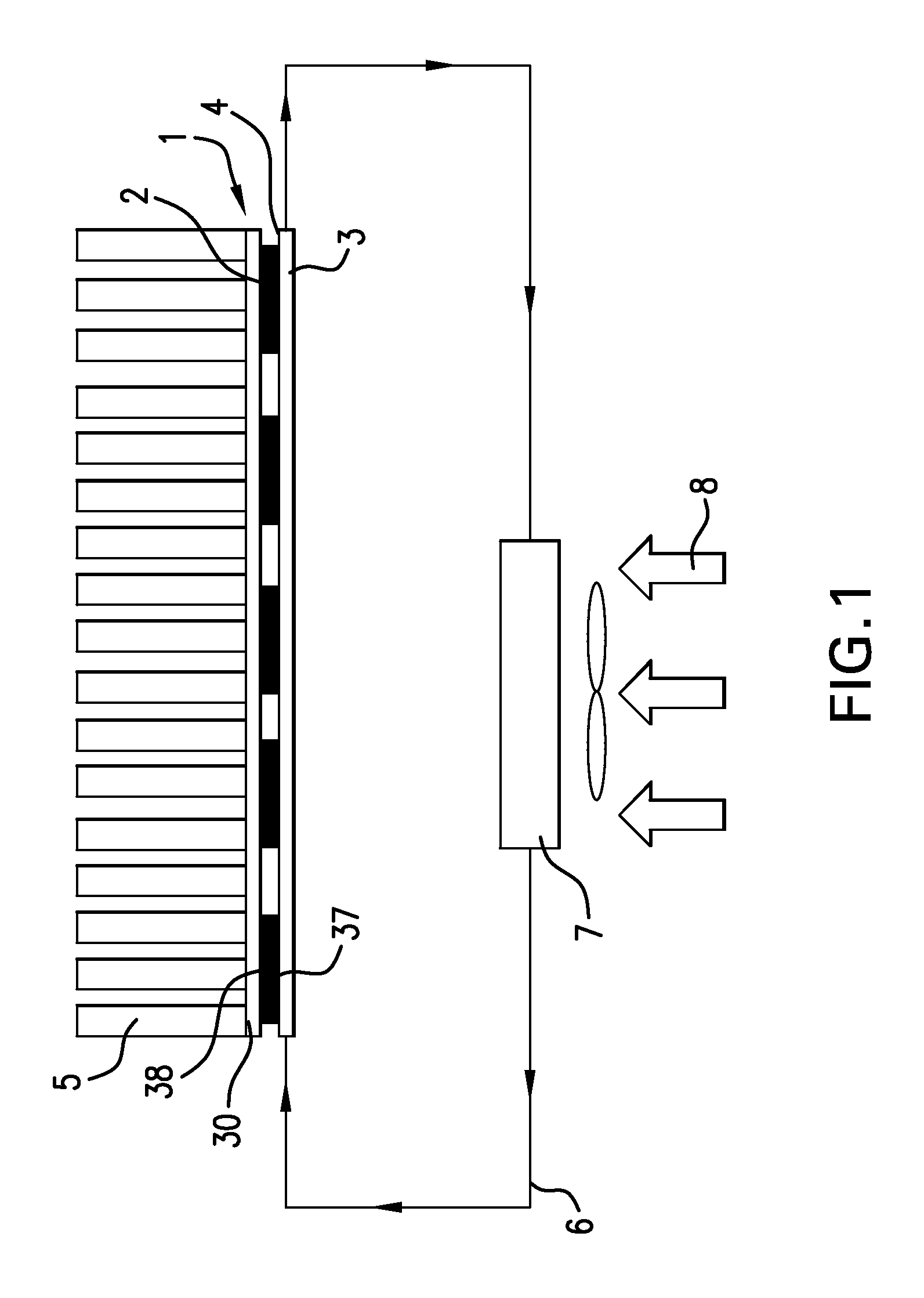
[0048]FIG. 1 shows a schematic view of a thermoelectric temperature control unit 1. In FIG. 1, the thermoelectric temperature control unit 1 is shown in section and, since the intention is to illustrate only the principle of the thermoelectric temperature control unit 1, it is not shown fully.

[0049]Arranged above the thermoelectric temperature control unit 1 is a plurality of battery elements 5, the temperature of which the thermoelectric temperature control unit 1 serves to control. The thermoelectric temperature control unit 1 consists essentially of a plurality of Peltier elements 2, which are capable of transferring heat from one of the outer surfaces thereof to the opposite outer surface through the application of a voltage. The battery elements 5 can thereby be either cooled or heated.

[0050]The focus of the invention is on the cooling of the battery elements 5. In order to be able to dissipate the heat absorbed by the battery elements 5 from the thermoelectric temperature cont...


PUM


Abstract

The application relates to thermoelectric temperature control units, for example for controlling the temperature of an energy storage device in a motor vehicle. An exemplary embodiment comprises a Peltier element, having a first and a second surface, wherein the second surface is substantially adjacent or opposite to the first. The first surface is connected in a thermally conductive manner to a first and/or second flow duct, through which a fluid can flow. The second surface is connected in a thermally conductive manner to a heat-producing element, wherein the first flow duct is in fluid communication at one of the ends thereof with a first header, and the second flow duct is in fluid communication at one of the ends thereof with a second header, and the first flow duct and the second flow duct are in fluid communication at the respective second ends thereof with a common reversing header.

Description

TECHNICAL FIELD[0001]A thermoelectric temperature control unit, in particular for controlling the temperature of an energy storage device in a motor vehicle, having at least one first Peltier element, which has a first surface and a second surface substantially adjacent or opposite to the first surface, wherein the first surface is connected in a thermally conductive manner to at least one first flow duct and / or one second flow duct, is advantageous.PRIOR ART[0002]Motor vehicles with electric additional drives or fully electric drives generally require electric energy storage devices. In order to keep these electric energy storage devices within an optimum temperature window at all times in respect of the performance thereof, these energy storage devices must be periodically cooled or heated, depending on ambient conditions.[0003]In this context, there are demanding requirements on the homogeneity of the temperature distribution within the energy storage device in order, on the one ...

Claims


Application Information

Patent Timeline
IPC IPC(8): F25B21/02
CPCF25B21/02F28D1/05375F28D2021/0029F28F9/02F28F9/0221F28F9/0278F28F9/028H01M2220/20H01M10/613H01M10/625H01M10/6556H01M10/6568H01M10/6572Y02E60/10
Inventor GRUNWALD, JURGENNEFF, HEIKONEUMEISTER, DIRKWEHOWSKI, MANUELSTEINBACH, MARTINMOLDOVAN, FLORIN
Owner MAHLE INT GMBH
Why Eureka
Try Eureka