
Plating apparatus

Inactive Publication Date: 2014-01-16
SAMSUNG ELECTRO MECHANICS CO LTD
View PDF1 Cites 0 Cited by
  • Summary
  • Abstract
  • Description
  • Claims
  • Application Information

AI Technical Summary

Benefits of technology

The present invention aims to provide a plating apparatus that can significantly decrease process time and lower costs.

Problems solved by technology

In this case, current is concentrated on an end of the article to be plated to concentratedly electrodeposite the metal ions on the end of the article to be plated, thereby causing plating deviation.
Therefore, a uniform plating thickness cannot be obtained.

Method used


Image

  • Plating apparatus
  • Plating apparatus
  • Plating apparatus

Examples


Embodiment Construction

[0032]The objects, features and advantages of the present invention will be more clearly understood from the following detailed description of the preferred embodiments taken in conjunction with the accompanying drawings. Throughout the accompanying drawings, the same reference numerals are used to designate the same or similar components, and redundant descriptions thereof are omitted. Further, in the following description, the terms “first,”“second,”“one side,”“the other side” and the like are used to differentiate a certain component from other components, but the configuration of such components should not be construed to be limited by the terms. Further, in the description of the present invention, when it is determined that the detailed description of the related art would obscure the gist of the present invention, the description thereof will be omitted.

[0033]Hereinafter, preferred embodiments of the present invention will be described in detail with reference to the attached...


PUM


Abstract

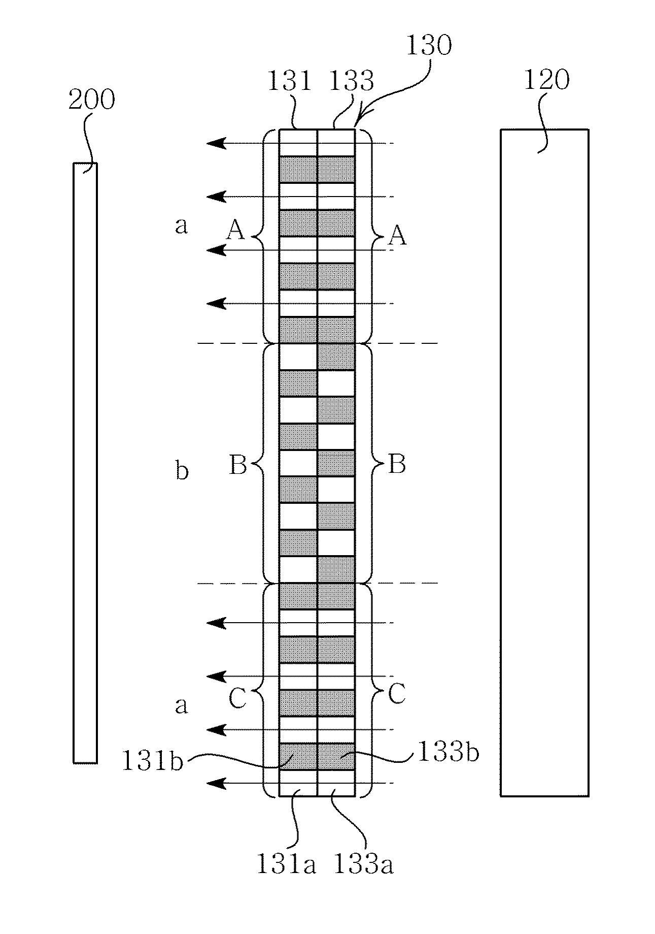
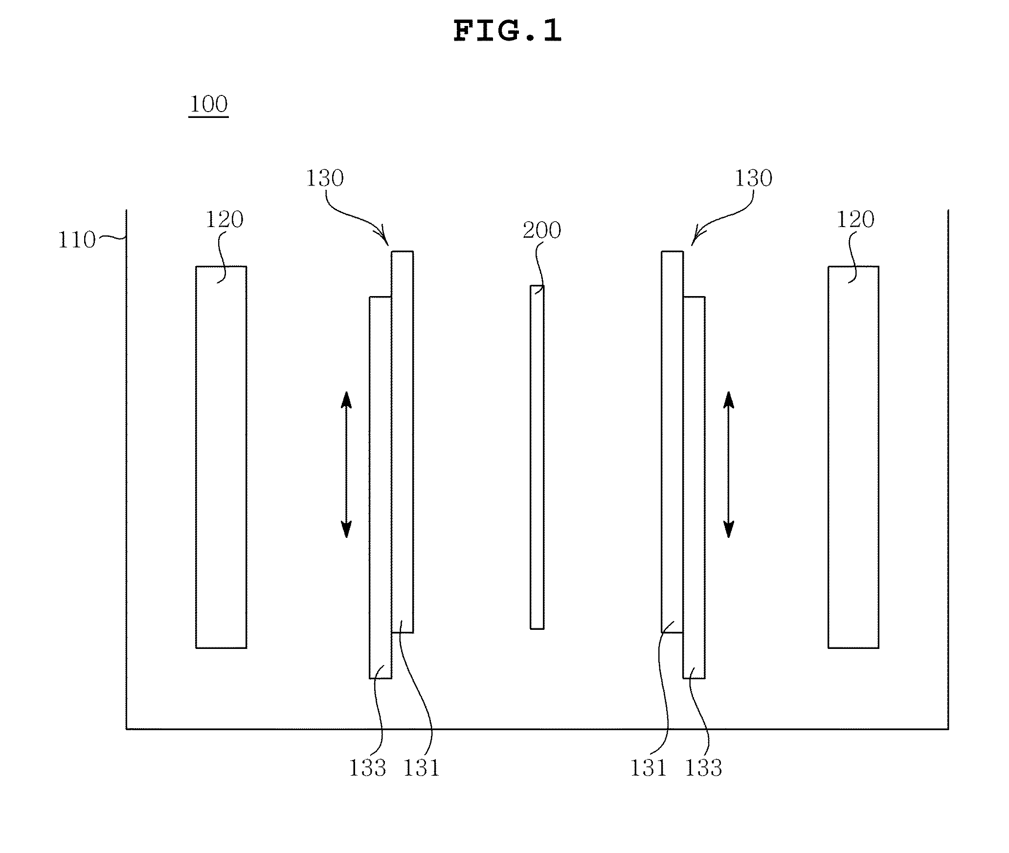
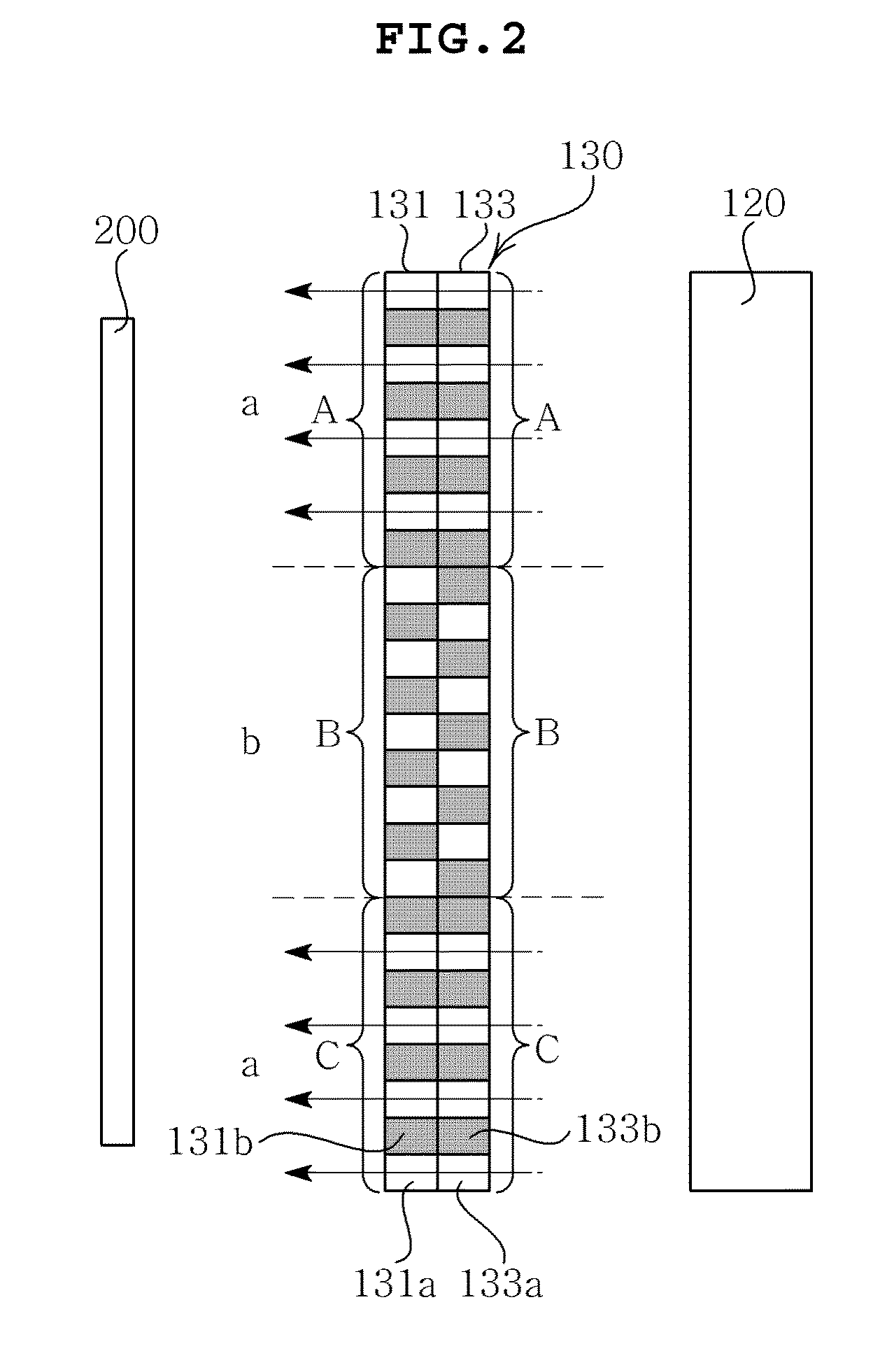
Disclosed herein is a plating apparatus, including: a plating tank receiving a plating solution and having an article to be plated injected thereinto; an anode disposed to face one surface or both surfaces of the article to be plated; and a shielding member disposed between the article to be plated and the anode and configured of a first plate and a second plate adjacently disposed to the first plate, the first plate and the second plate moving in parallel with each other.

Description

CROSS REFERENCE TO RELATED APPLICATION[0001]This application claims the benefit of Korean Patent Application No. 10-2012-0076608, filed on Jul. 13, 2012, entitled “Plating Apparatus” which is hereby incorporated by reference in its entirety into this application.BACKGROUND OF THE INVENTION[0002]1. Technical Field[0003]The present invention relates to a plating apparatus.[0004]2. Description of the Related Art[0005]Electroplating may be used to protect a metallic ornament or surface and has been used in various fields such as electronic components, a printed circuit board, a circuit formation of a semiconductor device, and the like.[0006]The electroplating may form a plating layer by dipping an article to be plated in a plating solution to make the article to be plated as a cathode and a metal to be electrodeposited as an anode and electrodepositing desired metal ions on a surface of an article to be plated according to application of current.[0007]In this case, current is concentrat...

Claims


Application Information

Patent Timeline
IPC IPC(8): C25D17/02
CPCC25D17/001C25D17/008C25D5/02C25D17/02
Inventor ROH, YOU JUNGKIM, CHUL KYU
Owner SAMSUNG ELECTRO MECHANICS CO LTD
Learn More