Cast-steel pouring apparatus

a technology of pouring apparatus and cast steel, which is applied in the direction of casting apparatus, melt-holding vessels, manufacturing tools, etc., can solve the problems of shortening casting time and difficult operation, and achieve the effect of reducing fluctuations, and efficiently causing molten steel to discharg

Inactive Publication Date: 2014-01-16
AISIN TAKAOKA CO LTD +2
View PDF2 Cites 2 Cited by
  • Summary
  • Abstract
  • Description
  • Claims
  • Application Information

AI Technical Summary

Benefits of technology

[0030]As explained above, in accordance with the present invention, the first pivot driving source is driven to cause the furnace body to pivot about the first axial line of the first pivot shaft, which serves as the pivotal center, in the steel-outing direction at the time of steel outing, thereby causing the molten steel in the retainer chamber to discharge from the steel-outing leading end of the steel-outing trough unit in the furnace body. The molten steel, which has been discharged, is received by the sprue of casting mold. Upon thus outing steel, it is possible to shorten a distance between the steel-outing leading end of the steel-outing trough unit and the first axial line of the first pivot shaft, and accordingly it is possible to make a pivotal radius smaller for causing the steel-outing leading end of the steel-outing trough unit to pivot.
[0031]Since it is possible to thus make the pivotal radius for the steel-outing leading end of the steel-outing trough unit smaller, it is possible to reduce fluctuations as well in the pouring angle for causing molten steel to pour with respect to casting mold; and accordingly it is possible to efficiently cause molten steel to discharge with respect to the casting mold's sprue as aimed at within a short period of time, upon casting the molten steel in a singularity of casting mold. Moreover, even when casting molten steel into a plurality of casting molds, it is possible to efficiently cause the molten steel to discharge with respect to the respective casting molds'sprue as aimed at within a short period of time. By means of these, upon casting molten steel with respect to a casting mold, and furthermore upon casing molten steel into a plurality of casting molds, it is possible to set up a molten-steel retaining temperature lower, at which molten steel is retained in the retainer chamber of the furnace body, as much as possible, because it is possible to shorten a casting time for casting molten steel into casting mold. It is eventually possible to set up a melting temperature lower as much as possible upon causing molten steel to melt by melting furnace, and accordingly it is possible to contribute to reductions in costs required for melting steel. In addition, it is possible to contribute to causing fluctuations to reduce in the molten-steel casting speed, because it is possible to intend shortening also in the steel-outing trough unit3 s trough length.
[0032]As aforementioned, since it is possible to make a casting temperature of molten steel lower as much as possible upon casting molten metal of cast steel in accordance with the present invention, it is possible to keep down reactions between materials for casting mold, such as casting sands, and molten steel. Accordingly, it is possible to suppress the seizure phenomenon where casting sands have seized onto cast steel's casting surfaces, and consequently it is possible to contribute to improvements in casting surfaces on the resulting cast steel. In addition, it is possible to reduce shrinkage defects in the resultant cast steel, because it is possible to make a casting temperature of molten steel lower as much as possible.

Problems solved by technology

In the technique concerning Patent Literature No. 1, however, since the furnace body does not comprise any steel-outing trough unit for causing the molten metal to discharge, it is not easy to identify the drop position onto which the molten metal drops, and accordingly there are limitations in order for causing the casting time to shorten.

Method used


Image

  • Cast-steel pouring apparatus
  • Cast-steel pouring apparatus
  • Cast-steel pouring apparatus

Examples


Embodiment Construction

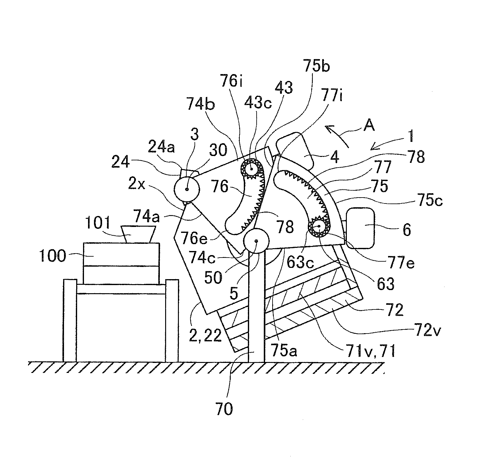
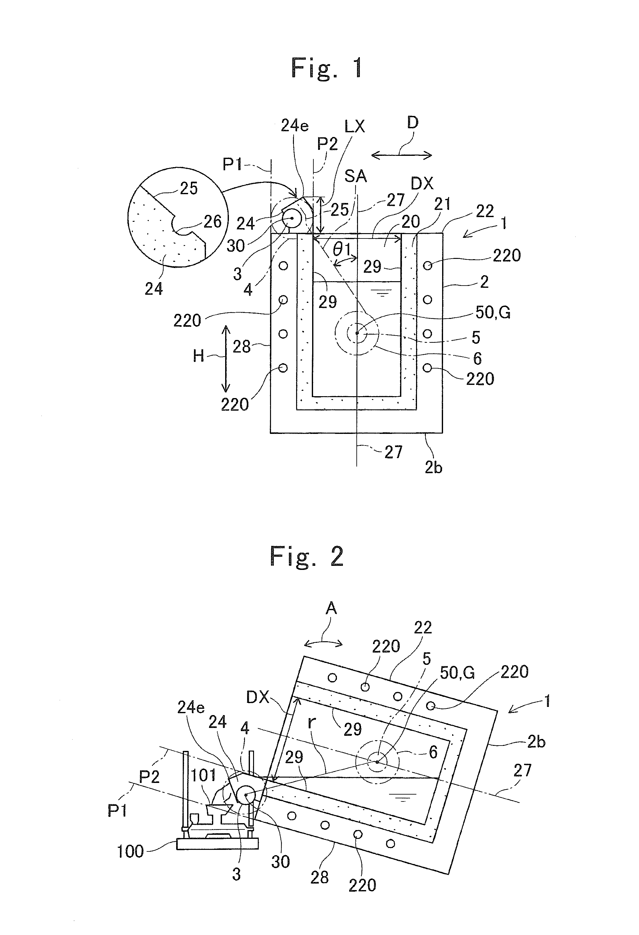
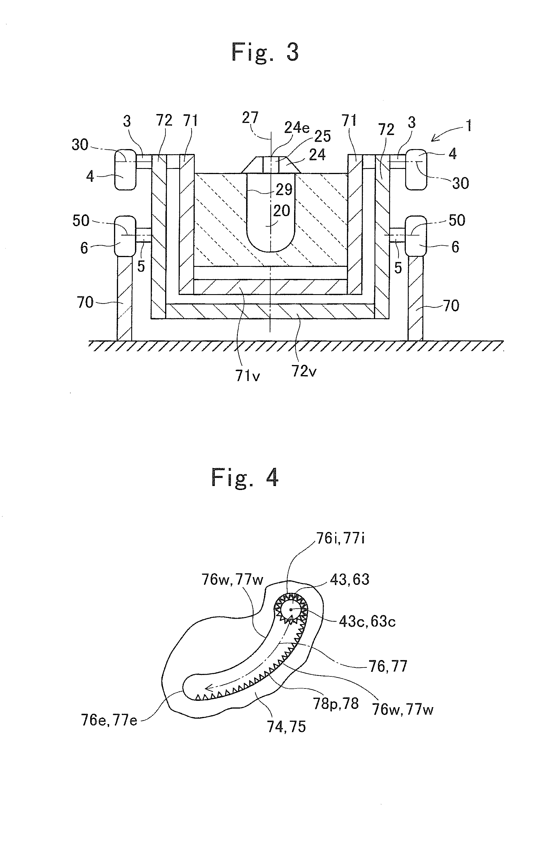
[0046]In a standby state where a furnace body is put in place so as to make the center line of the furnace body orient along the vertical direction, a first axial line of a first pivot shaft is positioned on a more diametrically inner side than is a first imaginary extension line of an outer-circumference wall face in a furnace-body main body, and is positioned on a more diametrically outer side than is a second imaginary extension line of an inner-circumference wall face in a fire-retardant lining material that the furnace-body main body has. In addition, a steel-outing leading end of a steel-outing trough unit is positioned on a more diametrically inner side than is the first imaginary axial line of the outer-circumference wall face in the furnace-body main body, and is positioned on a more diametrically outer side than is the second imaginary extension line of the inner-circumference wall face in the fire-retardant lining material that the furnace-body main body has. The furnace ...


PUM

PropertyMeasurementUnit
diameteraaaaaaaaaa
timeaaaaaaaaaa
distanceaaaaaaaaaa

Abstract

A cast-steel pouring apparatus is provided, cast-steel pouring apparatus which can contribute to shortening a casting time for casting molten steel of cast steel into a sprue of casting mold. A first axial line of a first pivot shaft is positioned on a more diametrically inner side than is a first imaginary extension line of an outer-circumference wall face in a furnace-body main body, and is positioned on a more diametrically outer side than is a second imaginary extension line of an inner-circumference wall face in a fire-retardant lining material that the furnace-body main body has. As a steel-outing trough unit protrudes from a furnace body upward or upward and outward obliquely, a steel-outing leading end of the steel-outing trough unit is positioned on a more diametrically inner side than is the first imaginary extension line of the outer-circumference wall face in the furnace-body main body, and is positioned on a more diametrically outer side than is the second imaginary extension line of the inner-circumference wall race in the fire-retardant lining material that the furnace-body main body has.

Description

TECHNICAL FIELD[0001]The present invention relates to a cast-steel pouring apparatus for casting molten steel of cast steel, whose solidification initiation temperature is higher than that of cast iron, into a casting mold.BACKGROUND ART[0002]It has been said that it is not necessarily easy to cast molten steel of cast steel whose carbon content is less than that of cast iron in order to manufacture cast-steel products in defect-free-product state as reducing defective fractions. This results from the fact that, unlike cast iron, since molten steel of cast steel whose carbon content is less has a high solidification initiation temperature, a casting temperature of molten steel is high, and so on. When such a circumstance is taken into consideration, it has been requested for molten steel of cast steel that the casting be completed within a shorter period of time as much as possible.[0003]Patent Literature No. 1 discloses a casting apparatus, although it is not one which is limited t...

Claims


Application Information

Patent Timeline
Patent Type & Authority Applications(United States)
IPC IPC(8): B22D41/06B22D41/01
CPCB22D41/06B22D41/01
Inventor SATO, TAKAHIROCYOMATSUKEN, SHINICHIZHANG, ZHONG-ZHIHANAI, TORUTERADA, HIDETOKATO, MASAYUKIHATTORI, HIDEMI
Owner AISIN TAKAOKA CO LTD
Why Eureka
Try Eureka