Eureka AIR delivers breakthrough ideas for toughest innovation challenges, trusted by R&D personnel around the world.

Magnetic damper

Active Publication Date: 2014-01-16
RENTON COIL SPRING
View PDF2 Cites 13 Cited by
  • Summary
  • Abstract
  • Description
  • Claims
  • Application Information

AI Technical Summary

Benefits of technology

The present invention provides a way to reduce movement by using magnetic forces to damp out vibrations or oscillations. This technology can be used in a variety of applications such as automotive shock absorbers, bicycle dampers, and aircraft shocks. It uses a nonferrous metallic member and a ferrous member to generate a magnetically induced current, which results in a damping effect on the movement. The invention also allows for variable resistance control of movement by either altering the magnetic properties of the metallic members or adding an electromagnet to change the damping effect. This magnetic damping system does not require the use of fluids or complex parts, reducing friction, noise, and fatigue rate.

Problems solved by technology

After extended periods of use, however, these systems are susceptible to fatigue and deterioration, causing problems of noise, short life, and leakage.
Many hydraulic systems utilizing complex valve systems suffer from the ability to quickly absorb pressure “spikes” and consequent harshness of ride and movement.
Furthermore, leaks and broken seals can contribute to breakdown of the system while in motion.
This could cause damage to the system and serious bodily harm to an operator.
Because of the numerous, complex moving parts in existing systems, they operate under high temperatures due to friction, therefore causing greater fatigue and deterioration.
Many shock absorbing systems, including simple spring systems, lack the capability to provide variable resistance control to movement depending upon a desired resistance at particular moments of force.
Existing systems that can provide variable control resistance include complex valve mechanisms and moving parts that suffer from the same problems.
Thus, there are unmet needs in the art for damping movement.

Method used


Image

  • Magnetic damper
  • Magnetic damper
  • Magnetic damper

Examples


Embodiment Construction

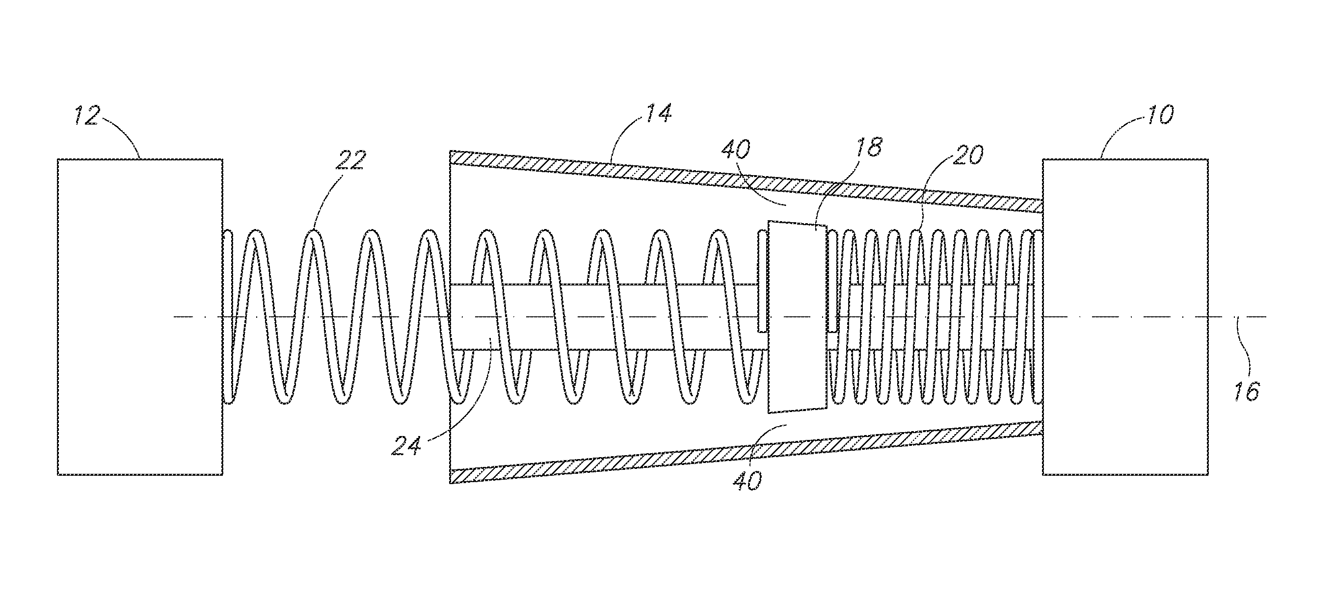
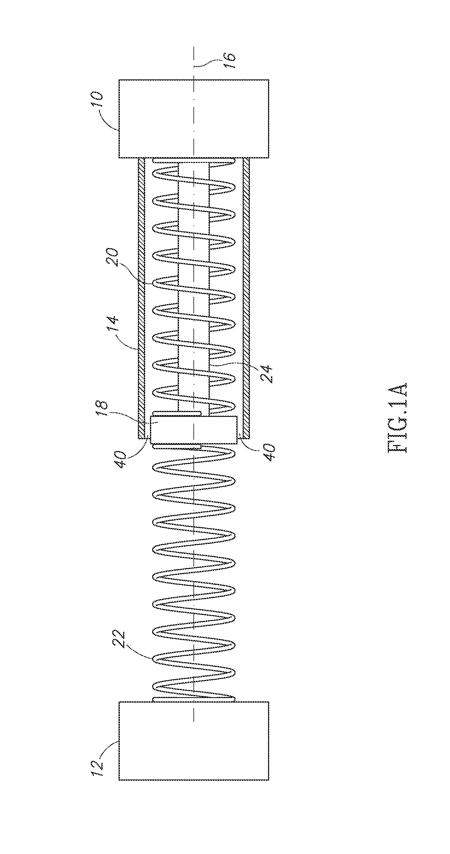
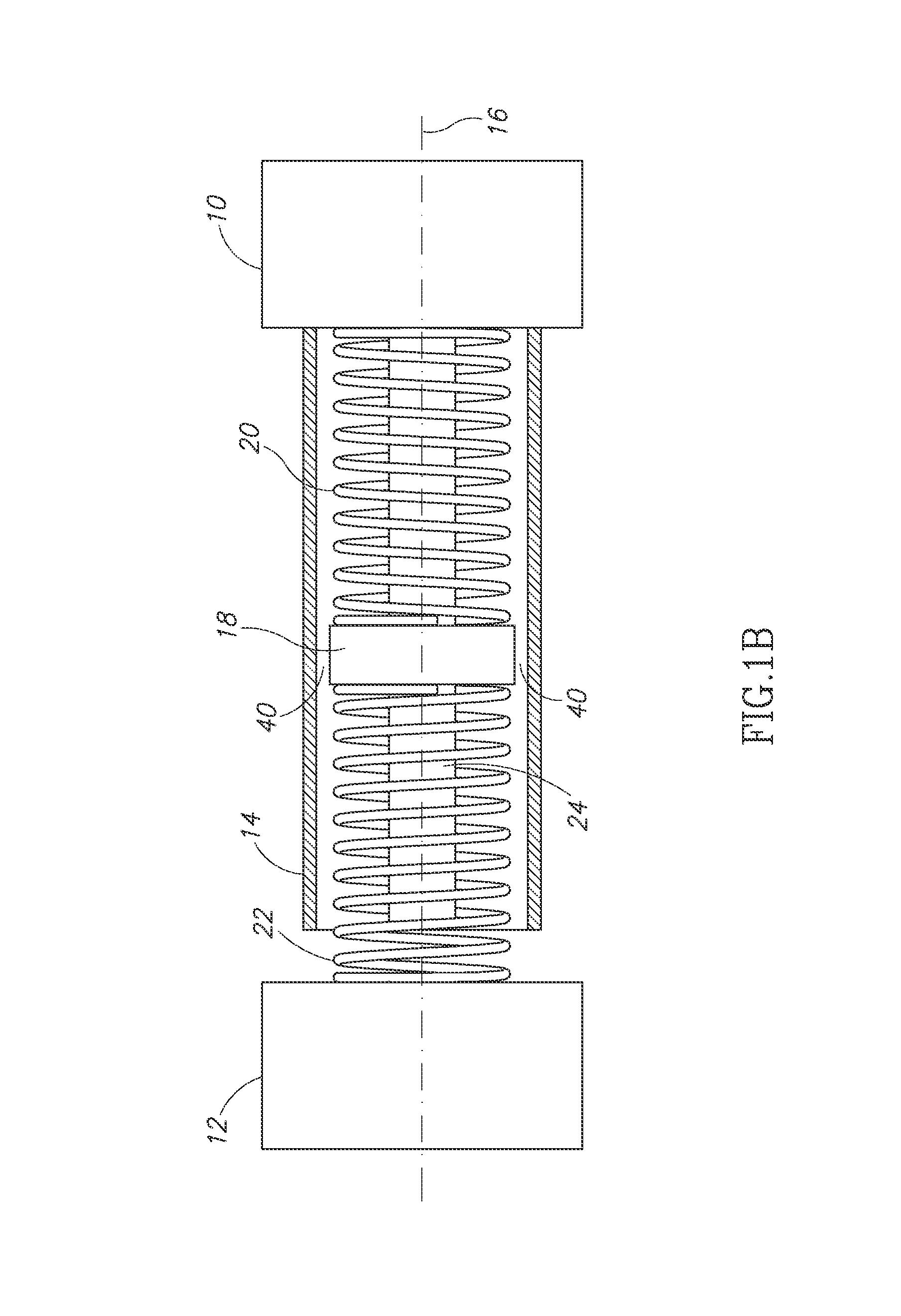
[0027]By way of overview, the present invention provides apparatuses, systems, and methods for magnetically damping movement of a first mass relative to a second mass. In one presently preferred embodiment, the invention generates magnetically induced current to damp movement of the first mass relative to the second mass. This is accomplished through causing movement of a nonferrous member about an axis of a ferrous member, wherein the nonferrous member is coupled to the first mass and the ferrous member is coupled to the second mass (or vice versa). Because the ferrous member and nonferrous member are in close proximity, upon movement an induced current is generated in the nonferrous member that damps movement of the ferrous member, consequently damping movement of the first mass relative to the second mass.

[0028]In another embodiment, the magnetically induced damping effect is accomplished through including an electromagnet to provide variable control over resistance to movement. ...


PUM


Abstract

Apparatus, systems, and methods for damping movement of a first mass relative to a second mass by magnetically generating induced current are provided. A magnet is coupled to one mass and a nonferrous metallic member is coupled to another mass that moves relative to the first mass. First and second springs are coupled to opposing ends of the magnet, the magnet being positioned between the springs. A guide member channels the magnet as it moves relative to the nonferrous member, the magnet being slidable along the guide member. The magnet is in close proximity to the nonferrous metallic member as the magnet moves. Upon causing movement of the magnet by either mass, the magnet generates an electrical current in the nonferrous metallic member that induces a counter magnetic field that opposes the magnetic field generated by the current to damp movement of the magnet as it moves.

Description

PRIORITY CLAIM[0001]This application claims priority from U.S. Provisional Application No. 61 / 385,944 filed on Sep. 23, 2010 entitled “Magnetic Damper.”FIELD OF THE INVENTION[0002]The present invention relates to damping systems such as shock absorbers, and more particularly, to a new magnetic damping system for resisting movement through generating induced currents.BACKGROUND OF THE INVENTION[0003]Existing damping systems typically employ a piston in a cylinder containing fluid to absorb shock. These hydraulic systems have multiple moving parts and valves. After extended periods of use, however, these systems are susceptible to fatigue and deterioration, causing problems of noise, short life, and leakage. Many hydraulic systems utilizing complex valve systems suffer from the ability to quickly absorb pressure “spikes” and consequent harshness of ride and movement. Furthermore, leaks and broken seals can contribute to breakdown of the system while in motion. This could cause damage ...

Claims


Application Information

Patent Timeline
IPC IPC(8): B60G13/02B60G17/06B60G15/04F16F7/00F16F15/03
CPCF16F6/005B60G13/02F16F15/03B60G17/06F16F7/00B60G15/04
Inventor PEPKA, CHARLES F.
Owner RENTON COIL SPRING
Why Eureka
Eureka Blog
Learn More