Large-particle inkjet dual-sign development printing

a technology of inkjet printing and large particles, applied in the direction of electrographic process apparatus, typewriters, instruments, etc., can solve the problems of low image density of printed images, limited use of purpose-made coated inkjet papers to improve image density, and inkjet inks that suffer from low image density, etc., to achieve low viscosity, high pigment concentration, and high viscosity. high

Inactive Publication Date: 2014-01-16
EASTMAN KODAK CO
View PDF5 Cites 7 Cited by
  • Summary
  • Abstract
  • Description
  • Claims
  • Application Information

AI Technical Summary

Benefits of technology

[0006]Several problems with inkjet inks have been identified. First, lithographic inks conventionally used for high-quality, high-volume printing are highly viscous and contain a high concentration of pigment. In contrast, inkjet inks have low viscosity in order to be able to be jetted from an inkjet nozzle or head. Typical inkjet inks contain at most 10% solid colorants. Since inkjet inks penetrate into the paper and have low colorant concentrations, such prints often suffer from low image density. In contrast, images printed by lithographic (litho) and electrophotographic (EP) processes have high density, and correspondingly higher image quality. In litho and EP printers, the ink, colorant, or marking particulate matter resides on the surface of the paper, thereby blocking light from reaching the paper fibers. Prior schemes using purpose-made coated inkjet papers to attempt to improve image density are limited in the type of paper that can be used, and coated inkjet papers are generally more expensive than standard commercial papers.

Problems solved by technology

Several problems with inkjet inks have been identified.
First, lithographic inks conventionally used for high-quality, high-volume printing are highly viscous and contain a high concentration of pigment.
Since inkjet inks penetrate into the paper and have low colorant concentrations, such prints often suffer from low image density.
Prior schemes using purpose-made coated inkjet papers to attempt to improve image density are limited in the type of paper that can be used, and coated inkjet papers are generally more expensive than standard commercial papers.
The large size of the ink droplet limits resolution and can produce image artifacts such as granularity and mottle.
(Small-drop-spread systems can also produce low-quality images because of the relatively lower proportion of the paper that is covered, e.g., as described in U.S. Pat. No. 5,847,721, which is incorporated herein by reference.)
Finally, despite large drop sizes, higher loadings of colorant or larger pigment particles cannot be used without compromising the jetting performance of the inkjet printer.
These limitations on ink composition prevent aqueous inkjet systems from producing glossy or raised-letter prints (which are examples of “special-effects” prints) that EP printers are capable of producing.
UV-curable inks are also not suited for as wide a range of substrates as aqueous inks.

Method used


Image

  • Large-particle inkjet dual-sign development printing
  • Large-particle inkjet dual-sign development printing
  • Large-particle inkjet dual-sign development printing

Examples


Embodiment Construction

[0041]Reference is made to commonly assigned, co-pending U.S. patent application Ser. Nos. 13 / 245,947, filed Sep. 27, 2011, entitled “INKJET PRINTER USING LARGE PARTICLES,” by Thomas N. Tombs, et al.; 13 / 245,971, filed Sep. 27, 2011, entitled “ELECTROGRAPHIC PRINTING USING FLUIDIC CHARGE DISSIPATION,” by Thomas N. Tombs, et al.; 13 / 245,957, filed Sep. 27, 2011, entitled “LARGE-PARTICLE INKJET PRINTING ON SEMIPOROUS PAPER,” by Thomas N. Tombs, et al.; 13 / 245,977, filed Sep. 27, 2011, filed, entitled “ELECTROGRAPHIC PRINTER USING FLUIDIC CHARGE DISSIPATION,” by Thomas N. Tombs, et al.; 13 / 245,964, filed Sep. 27, 2011, entitled “LARGE-PARTICLE SEMIPOROUS-PAPER INKJET PRINTER,” by Thomas N. Tombs, et al.; U.S. patent application Ser. No. 13 / 077,496, filed Mar. 31, 2011, entitled “DUAL TONER PRINTING WITH DISCHARGE AREA DEVELOPMENT,” by William Y. Fowlkes, et al.; and 13 / 245,931, filed Sep. 27, 2011, entitled “INKJET PRINTING USING LARGE PARTICLES,” by Thomas N. Tombs, et al.; the disclo...


PUM


Abstract

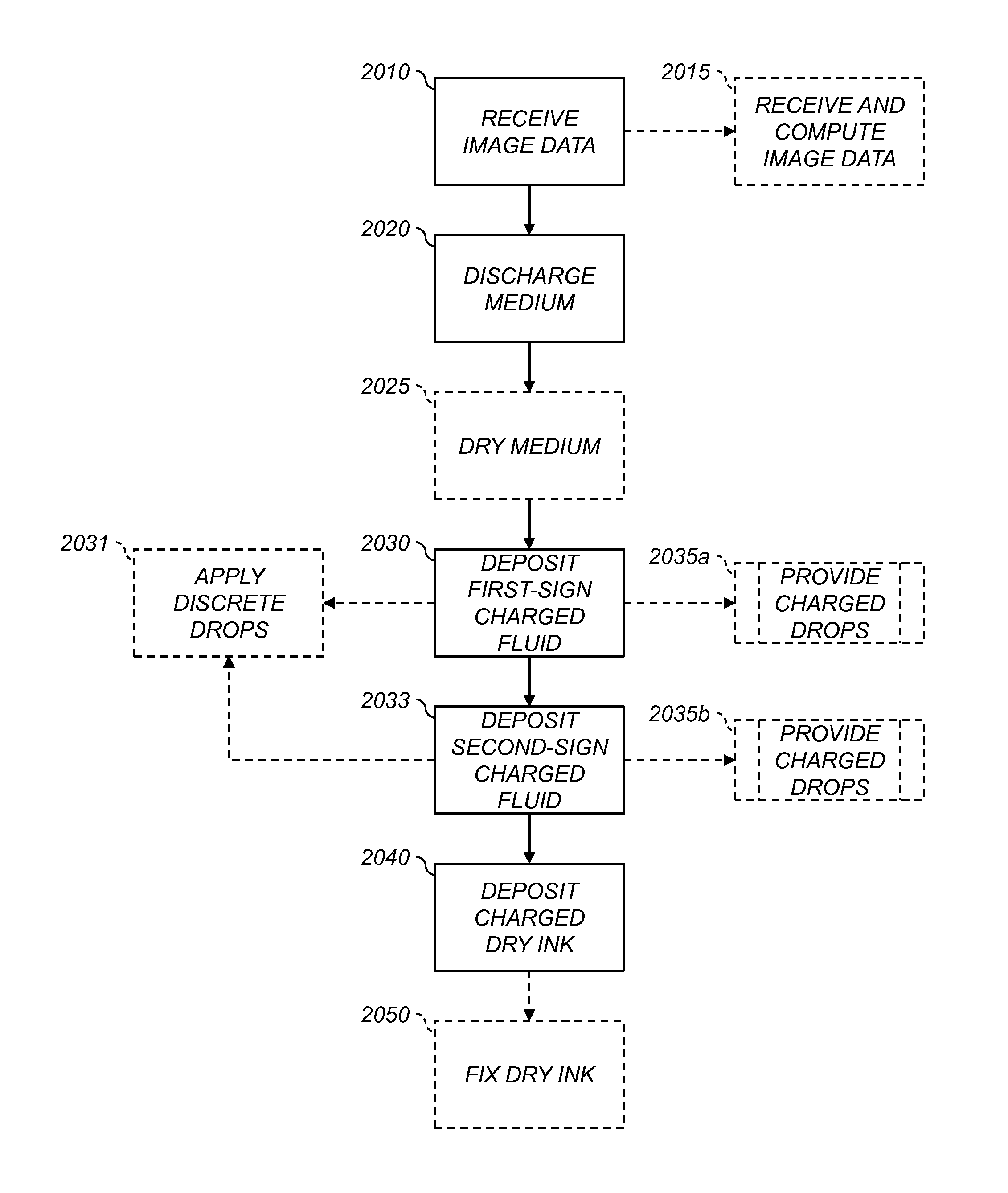
A method of producing a print on a recording medium includes receiving positive and negative image data for the print to be produced. A selected region of the recording medium is discharged. First-sign charged fluid is deposited in a selected first-sign charged-fluid pattern on the selected region of the recording medium, the first-sign charged-fluid pattern corresponding to the positive image data. Second-sign charged fluid is deposited in a selected second-sign charged-fluid pattern on the selected region of the recording medium, the second-sign charged-fluid pattern corresponding to the negative image data and the second sign being different from the first, sign. Charged dry ink having charge of the second sign is deposited onto the recording medium. The deposited dry ink is attracted to the first-sign charged-fluid pattern and adheres to the recording medium in the first-sign charged-fluid pattern.

Description

CROSS-REFERENCE TO RELATED APPLICATIONS[0001]Reference is made to commonly assigned, co-pending U.S. patent application Ser. No. ______ (Attorney Docket K000606), filed herewith, entitled “Large-Particle Inkjet Discharged-Area Development Printing,” by Michael Marcus, et al.; U.S. patent application Ser. No. ______ (Attorney Docket K000612), filed herewith, entitled “Large-Particle Inkjet Discharged-Area Development Printing,” by Michael Marcus, et al.; U.S. patent application Ser. No. ______ (Attorney Docket K001165), filed herewith, entitled “Intermediate Member For Large-Particle Inkjet Development,” by Michael Marcus, et al.; U.S. patent application Ser. No. ______ (Attorney Docket K001166), filed herewith, entitled “Large-Particle Inkjet Receiver-Charging Intermediate Member,” by Michael Marcus, et al.; the disclosures of which are incorporated by reference herein.FIELD OF THE INVENTION[0002]This invention pertains to the field of digitally controlled printing systems.BACKGROUN...

Claims


Application Information

Patent Timeline
Patent Type & Authority Applications(United States)
IPC IPC(8): B41J29/38B41J2/04
CPCB41J2/04B41J2/105B41J2/18B41J3/546G03G15/321
Inventor MARCUS, MICHAEL ALANPANCHAWAGH, HRISHIKESH V.
Owner EASTMAN KODAK CO
Why Eureka
Try Eureka