
Image correction system and method for multi-projection

a multi-projection and image correction technology, applied in the field of image correction systems and methods for multi-projection, can solve the problems of reducing the involvement of viewers in images, reducing the direction of the 3d effect that audiences feel is limited to the direction of the single screen, and reducing the heterogeneity of images

Active Publication Date: 2014-01-16
CJ 4DPLEX CO LTD
View PDF8 Cites 33 Cited by
  • Summary
  • Abstract
  • Description
  • Claims
  • Application Information

AI Technical Summary

Benefits of technology

The invention aims to create a new system and method for multi-projection that can reduce the different looks and feel of images created on multiple surfaces. The system analyzes the color, brightness, and quality of the images and corrects them to create a unified image on the entire surface. This creates a more uniform and seamless image that eliminates the need for additional steps to make the surfaces appear the same.

Problems solved by technology

However, audiences can only watch two-dimensional (2D) images under such a system.
However, these 3D technologies can provide audiences with 3D images, but the audiences just watch the images reproduced on a single screen, which may reduce the involvement in the images.
Moreover, the direction of the 3D effect that the audiences feel is limited to the direction of the single screen.
Furthermore, according to the conventional 3D technologies, the audiences must wear glasses equipped with polarizing filters during watching, which may make the audiences feel inconvenient, and different images are artificially presented to the left and right eyes, which may make some sensitive audiences feel dizzy or nausea.
However, the conventional projection systems, which are to simply use a single projection device, do not employ any correction technologies for creating these unified images.

Method used


Image

  • Image correction system and method for multi-projection
  • Image correction system and method for multi-projection
  • Image correction system and method for multi-projection

Examples


Embodiment Construction

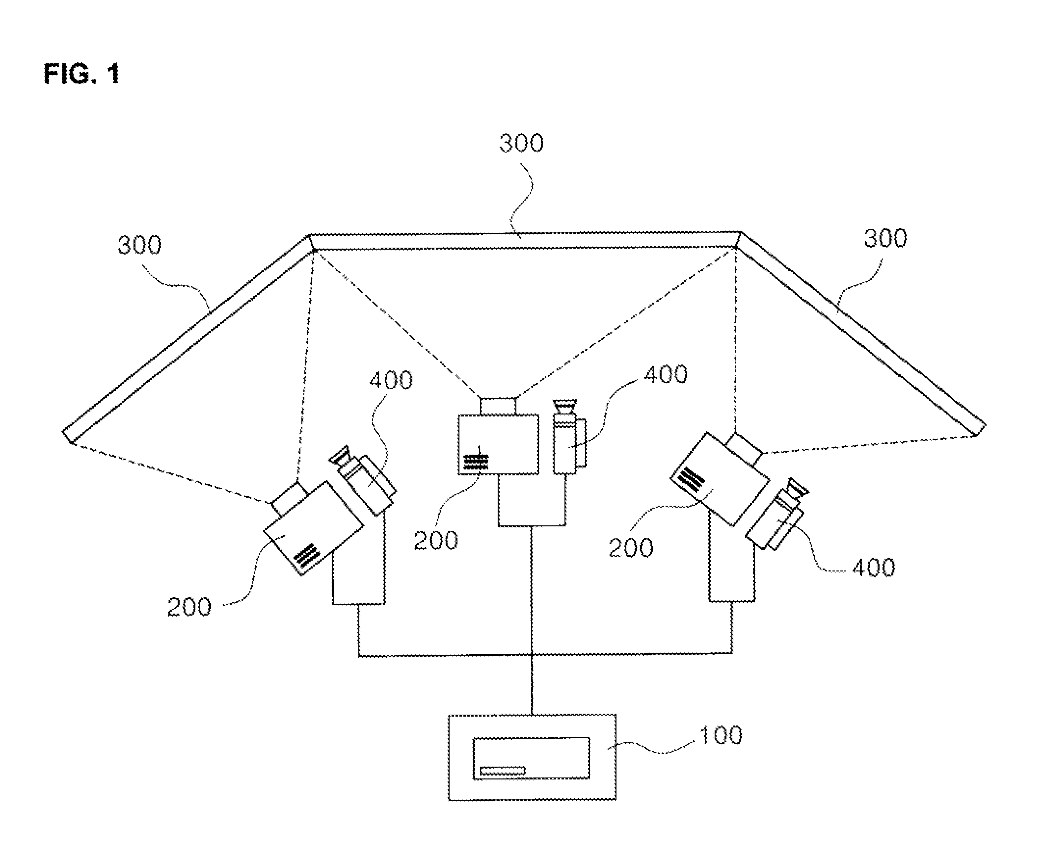
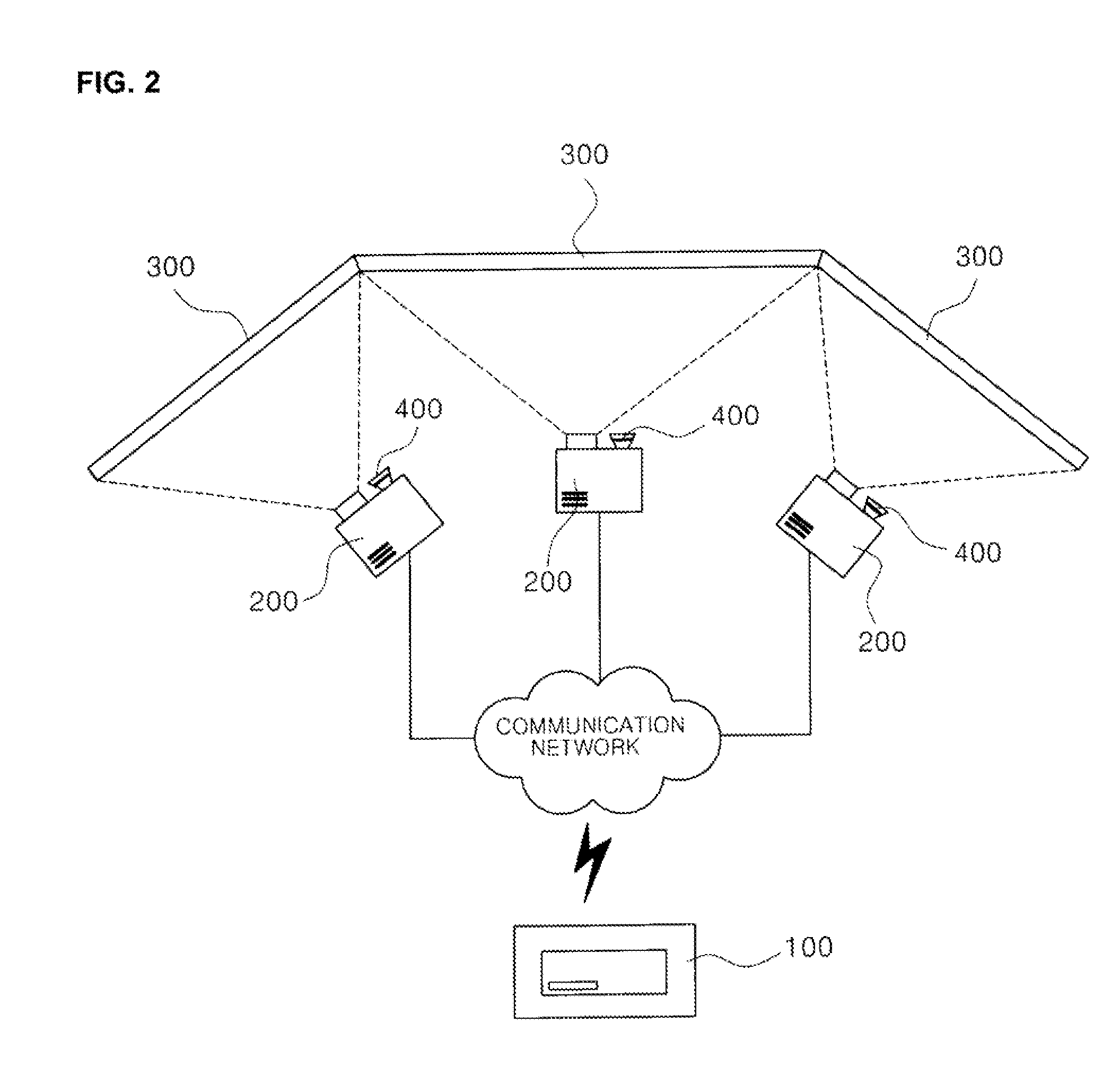
[0034]Hereinafter, an image correction system and method for multi-projection in accordance with embodiments of the present invention will be described in detail with reference to the accompanying drawings. The following embodiments are provided only for illustrative purposes so that those skilled in the art can fully understand the spirit of the present invention, but the present invention is not limited thereby. Moreover, it is to be understood that all matters herein set forth in the accompanying drawings are to be interpreted as illustrative and may be in different forms from those actually implemented.

[0035]Meanwhile, the term “comprising” specific components is an “open-ended term” that simply means that the corresponding components are present and should not be understood to exclude other additional components.

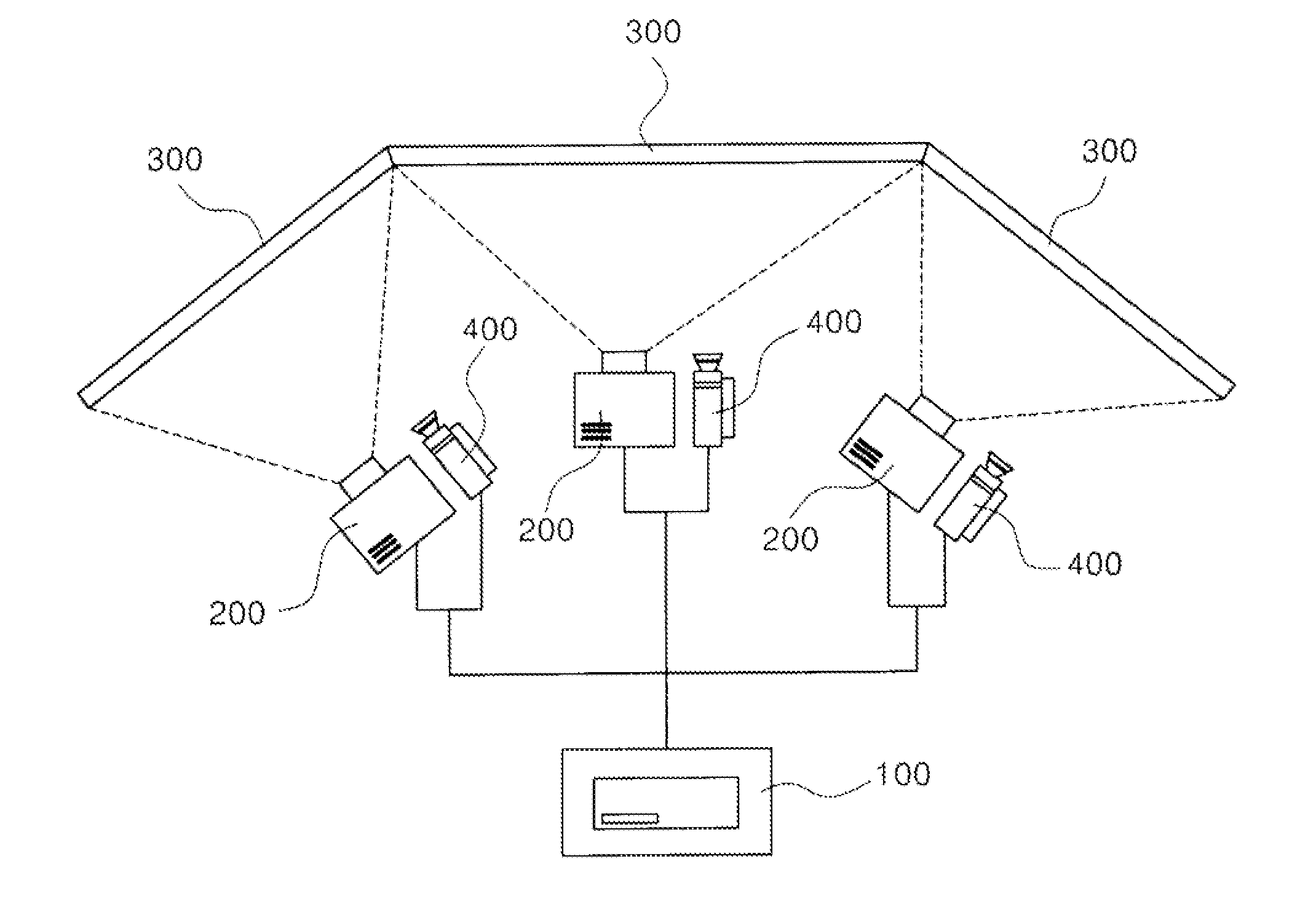
[0036]An image correction system in accordance with an embodiment of the present invention will be described with reference to FIGS. 1 to 5 below.

[0037]Referring to FIG...


PUM


Abstract

The present invention provides an image correction system and method for multi-projection, the image correction system including a plurality of projection surfaces which are installed in a single theater and a projection device which projects images on the plurality of projection surfaces, in which the images projected by the projection device on the plurality of projection surfaces are corrected based on relative differences in properties of the plurality of projection surfaces.

Description

CROSS-REFERENCE TO RELATED PATENT APPLICATION[0001]This application claims the benefit of Korean Patent Applications No. 10-2012-0076100 filed on Jul. 12, 2012, No. 10-2012-0130112 filed on Nov. 16, 2012, in the Korean Intellectual Property Office, the disclosure of which is incorporated herein in its entirety by reference.BACKGROUND OF THE INVENTION[0002]1. Field of the Invention[0003]The present invention relates to an image correction system and method for multi-projection and, more particularly, to an image correction system and method for multi-projection which can analyze relative differences in properties of a plurality of projection surfaces provided in a theater for multi-projection and correct images projected on the plurality of projection surfaces so as to offset the analyzed differences in properties.[0004]2. Description of the Related Art[0005]Conventionally, in order to reproduce images such as movies, advertisements, etc., two-dimensional images are projected on a si...

Claims


Application Information

Patent Timeline
Patent Type & Authority Applications(United States)
IPC IPC(8): G03B21/53
CPCG03B21/53G03B21/60H04N9/3147H04N9/3182H04N9/3194G03B37/04G03B21/005
Inventor KIM, HWAN CHULKANG, SU RYEON
Owner CJ 4DPLEX CO LTD
Learn More