Spread illuminating apparatus having two light conductive plates

a technology of illuminating apparatus and light conductive plate, which is applied in the direction of mechanical apparatus, lighting and heating apparatus, instruments, etc., can solve the problems of color filter still not coming up with a desired spectroscopic characteristic, and difficulty in commercially procuring high-output leds, etc., to eliminate color heterogeneity and coloration problems

Inactive Publication Date: 2006-11-16
MINEBEA CO LTD
View PDF1 Cites 10 Cited by
  • Summary
  • Abstract
  • Description
  • Claims
  • Application Information

AI Technical Summary

Benefits of technology

[0011] The present invention has been made in the light of the circumstances described above, and it is an object of the present invention to provide a spread illuminating apparatus which employs a plurality of point light sources having respective emission wavelengths different from one another, and which still is free from the color heterogeneity problem while enabling downsizing.
[0016] Accordingly, the lights emitted from the point light sources and introduced into each of the two light conductive plates are well mixed before exiting out from the light conductive plate, and when the two light conductive plates are stacked together, white light resulting from the sufficient mixture of the lights from the point light sources is achieved entirely across the light conductive plate placed atop, thus eliminating the color heterogeneity and coloration problem. And, if the light conductive plate is configured such that the thickness decreases from the first side surface to the second side surface, then the above-described advantage can be achieved with no substantial increase in dimension.

Problems solved by technology

The white LED has another problem that a white point varies largely depending on a fluorescent material (refer to, for example, paragraph of Japanese Patent Application Laid-Open No. 2003-58125).
The micro color filter method, however, has such a problem that the color filter still has not come up with a desired spectroscopic characteristic, and only one third of the light amount emitted from a spread illuminating apparatus is utilized (refer to, for example, paragraphs and [0003] of Japanese Patent Application Laid-Open No.
If the R-LED, the G-LED, and the B-LED are disposed individually at a side of a light conductive plate, lights, which are emitted from respective LEDs and enter the light conductive plate, exit out without duly getting mixed with one another at a region of the light conductive plate close to the side with the LEDs, which causes a problem of color heterogeneity and coloration (refer to, for example, pp.
With regard to the proposed solution (a), it is difficult to commercially procure high-output LEDs.
With regard to the solution (b), though a region suffering the color heterogeneity can be reduced, a region suffering uneven brightness distribution remains to exist (non-utilized region), and the stacking dimension of the LEDs constitutes the thickness dimension of the apparatus making it difficult to achieve a low-profile structure (for example, three LEDs for R, G and B make the thickness dimension trebled).
And, with regard to the solution (c), only a limited number of LEDs can be disposed at the corner of the light conductive plate, and also downsizing of the apparatus is restricted due to a non-utilized region generated in the light conductive plate.

Method used


Image

  • Spread illuminating apparatus having two light conductive plates
  • Spread illuminating apparatus having two light conductive plates
  • Spread illuminating apparatus having two light conductive plates

Examples


Embodiment Construction

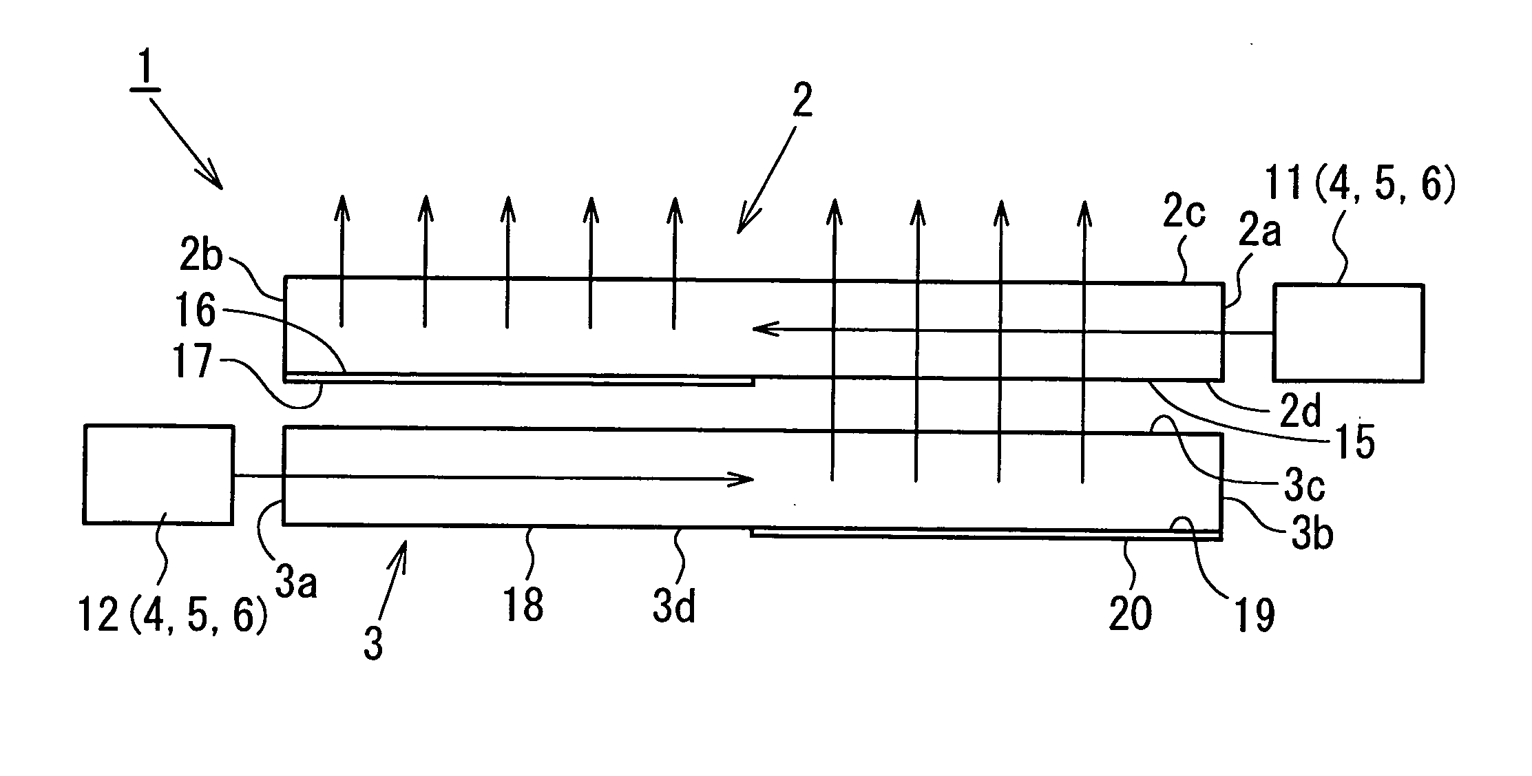
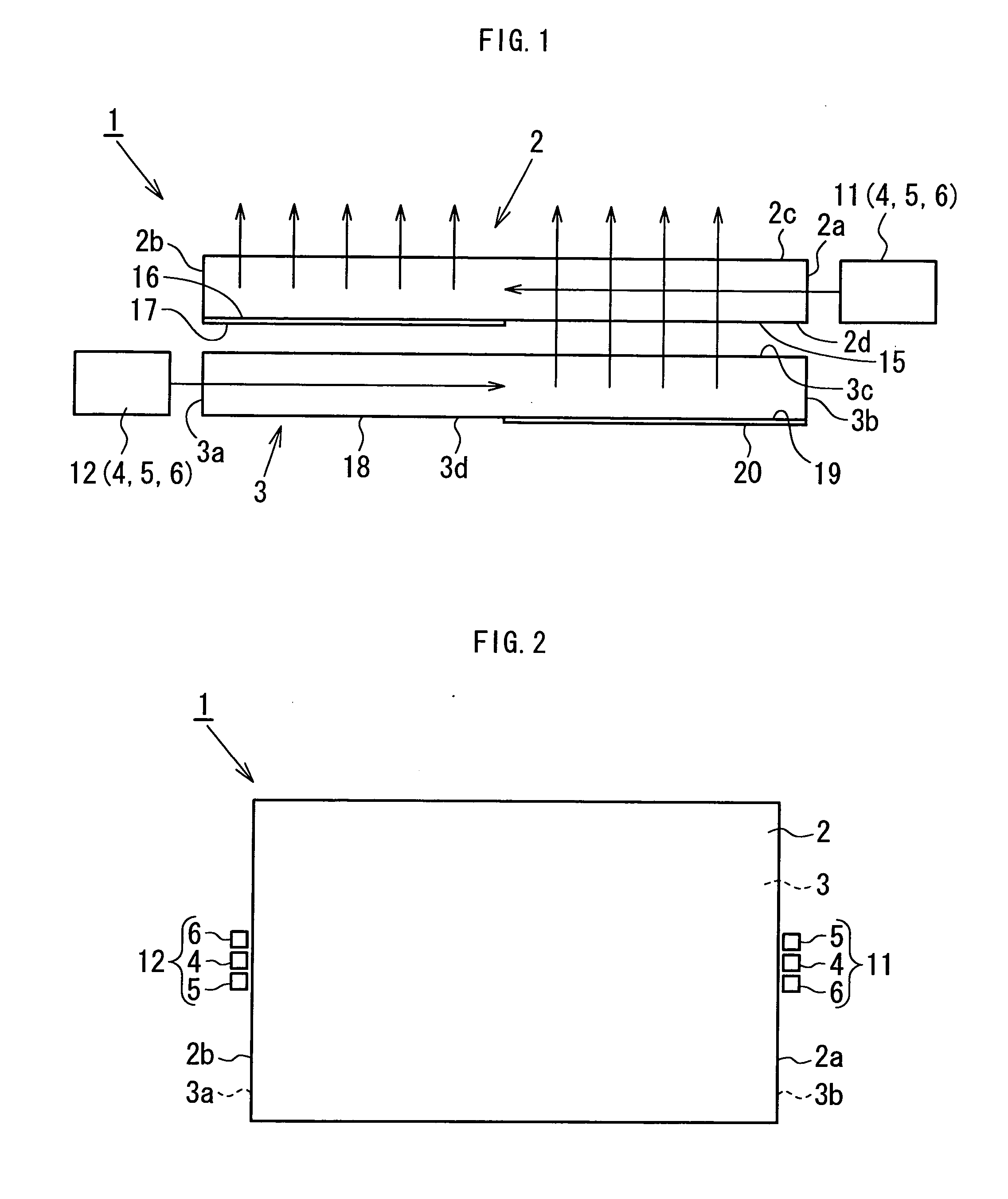
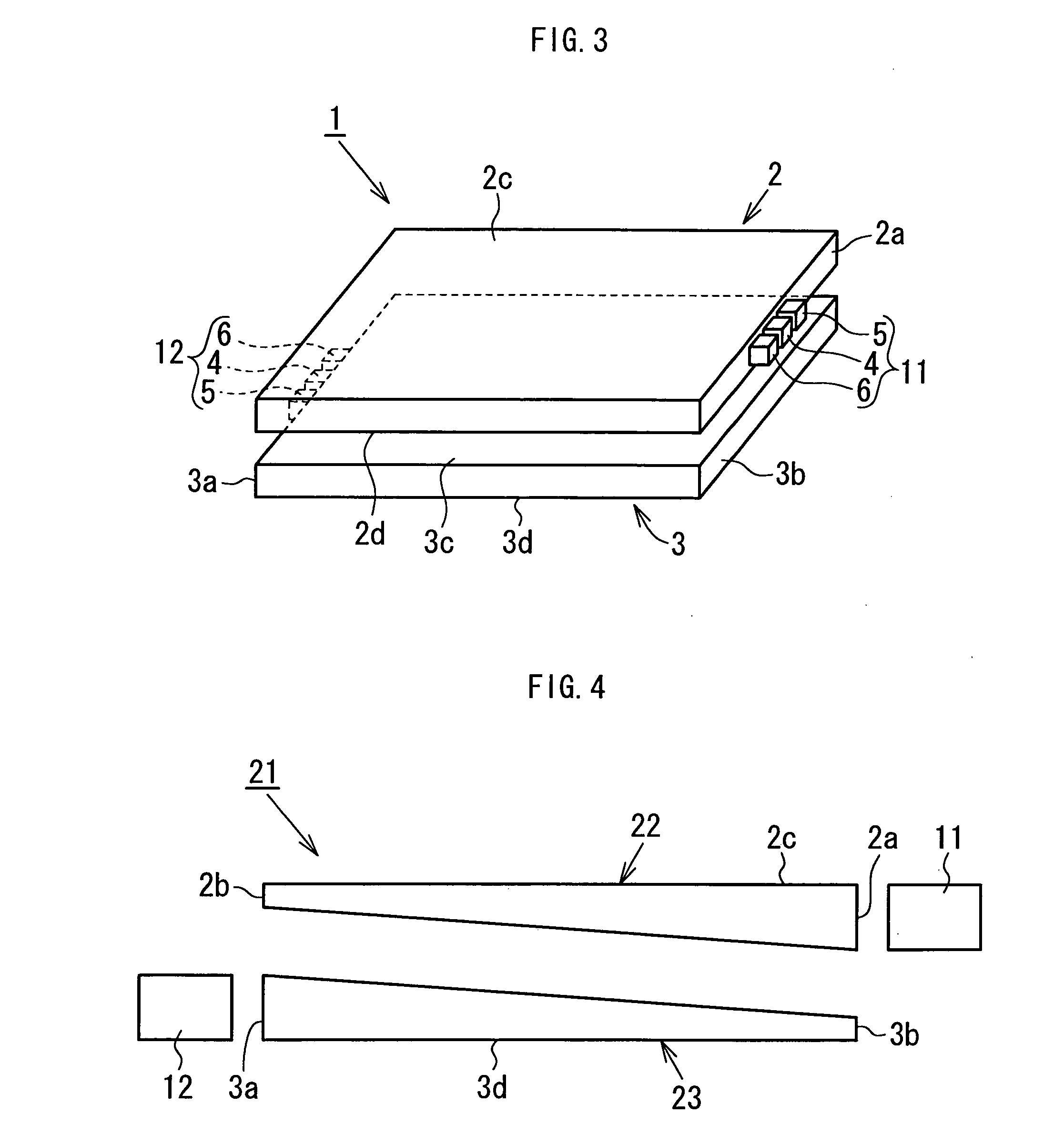
[0023] A first embodiment of the present invention will hereinafter be described with reference to FIGS. 1 to 3.

[0024] Referring to FIGS. 1 to 3, a spread illuminating apparatus 1 according to the first embodiment includes two light conductive plates (specifically, a first light conductive plate 2, and a second light conductive plate 3) substantially identical in configuration with each other.

[0025] A first RGB-LED unit 11, which includes a plurality (three in the present embodiment) of point light sources having respective different emission wavelengths (specifically, an R-LED 4 to emit a red light, a G-LED 5 to emit a green light, and a B-LED 6 to emit a blue light), is disposed at a first side surface 2a (right side in the figures) of the first light conductive plate 2. The first light conductive plate 2 defines a second other side surface 2b opposite to the first side surface 2a.

[0026] A second RGB-LED unit 12 structured identically with the first RGB-LED unit 11 is disposed ...


PUM

PropertyMeasurementUnit
distanceaaaaaaaaaa
distanceaaaaaaaaaa
emission wavelengthsaaaaaaaaaa

Abstract

A spread illuminating apparatus is provided that includes two light conductive plates. Each light conductive plate has point light sources having respective different emission wavelengths and disposed at one side surface thereof. Since a light exiting mechanism is formed at a region in one major surface of the light conductive plate located apart from the light sources, lights emitted from the light sources into the light conductive plate are adapted to exit out mostly from a region in the other major surface located apart from the light sources. The lights are allowed to be well mixed with one another before exiting out the light conductive plate, thus preventing the color heterogeneity and coloration problem. When the two light conductive plates are stacked together such that their respective one side surfaces are oppositely located apart from each other, white light is achieved entirely across the light conductive plate.

Description

BACKGROUND OF THE INVENTION [0001] 1. Field of the Invention [0002] The present invention relates to a side light type spread illuminating apparatus employing, as primary light sources, a plurality of light emitting diodes (LEDs) with respective different colors, such as red (R), green (G), and blue (B). [0003] 2. Description of the Related Art [0004] A side light type spread illuminating apparatus in which a white LED is disposed at a side of a light conductive plate is typically used in a liquid crystal display (LCD) apparatus for a mobile terminal device. The white LED is a wavelength conversion type LED (one-chip type LED) coupling a blue LED and a yellow fluorescent substance and is small in size and low in power consumption (refer to Japanese Patent Application Laid-Open No. H10-242513). [0005] The white LED has a problem with color rendering properties (refer to, for example, paragraph [0007] of Japanese Patent Application Laid-Open No. 2002-43633). The white LED has another ...

Claims


Application Information

Patent Timeline
Patent Type & Authority Applications(United States)
IPC IPC(8): H01L33/00F21S2/00F21V8/00F21Y101/02G02F1/13357
CPCG02B6/0061G02B6/4203G02B6/0073G02B6/0068
Inventor KUNIMOCHI, TORU
Owner MINEBEA CO LTD
Why Eureka
Try Eureka