
Purification of glucose concentration signal in an implantable fluorescence based glucose sensor

a fluorescence-based glucose sensor and glucose concentration technology, which is applied in the field of purification of glucose concentration signal in implantable fluorescence-based glucose sensors, can solve problems such as affecting the accuracy of glucose concentration measurement produced from raw signals

Active Publication Date: 2014-01-16
SENSEONICS INC
View PDF4 Cites 60 Cited by
  • Summary
  • Abstract
  • Description
  • Claims
  • Application Information

AI Technical Summary

Benefits of technology

The patent describes a method and system for using an optical sensor to determine the concentration of glucose in a living animal. The sensor is implanted in the animal and a light source emits excitation light to the indicator molecules in the sensor. The indicator molecules have an optical characteristic that responds to the concentration of glucose. The light is received by a photodetector and the received light is conveyed to a sensor reader. The sensor reader tracks the cumulative emission time of the excitation light and the implant time of the sensor. The received light is adjusted to compensate for offset and distortion, and the adjusted signal is converted to a measurement of glucose concentration in the animal. The technical effect is a more accurate and reliable method for determining glucose concentration in a living animal.

Problems solved by technology

The generated raw electrical signal may be indicative of the concentration of glucose in the medium surrounding the indicator molecules, but the raw signal may also include noise (e.g., offset and / or distortion) that affects the accuracy of the glucose concentration measurement produced from the raw signal.

Method used


Image

  • Purification of glucose concentration signal in an implantable fluorescence based glucose sensor
  • Purification of glucose concentration signal in an implantable fluorescence based glucose sensor
  • Purification of glucose concentration signal in an implantable fluorescence based glucose sensor

Examples


Embodiment Construction

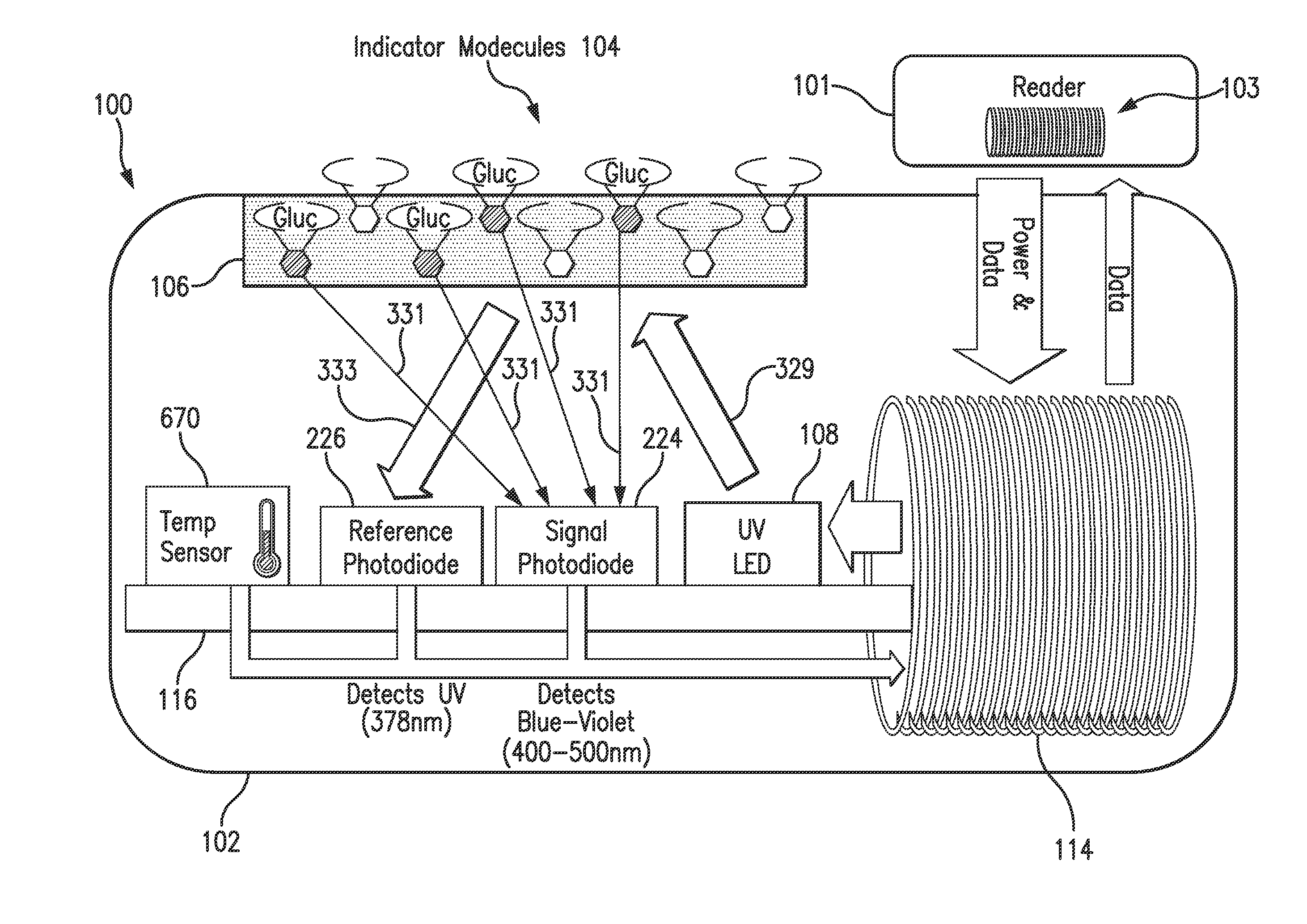
[0026]FIG. 1 is a schematic view of a sensor system embodying aspects of the present invention. In one non-limiting embodiment, the system includes a sensor 100 and an external sensor reader 101. In the embodiment shown in FIG. 1, the sensor 100 may be implanted in a living animal (e.g., a living human). The sensor 100 may be implanted, for example, in a living animal's arm, wrist, leg, abdomen, or other region of the living animal suitable for sensor implantation. For example, in one non-limiting embodiment, the sensor 100 may be implanted between the skin and subcutaneous tissues. In some embodiments, the sensor 100 may be an optical sensor (e.g., a fluorometer). In some embodiments, the sensor 100 may be a chemical or biochemical sensor.

[0027]A sensor reader 101 may be an electronic device that communicates with the sensor 100 to power the sensor 100 and / or obtain analyte (e.g., glucose) readings from the sensor 100. In non-limiting embodiments, the reader 101 may be a handheld r...


PUM


Abstract

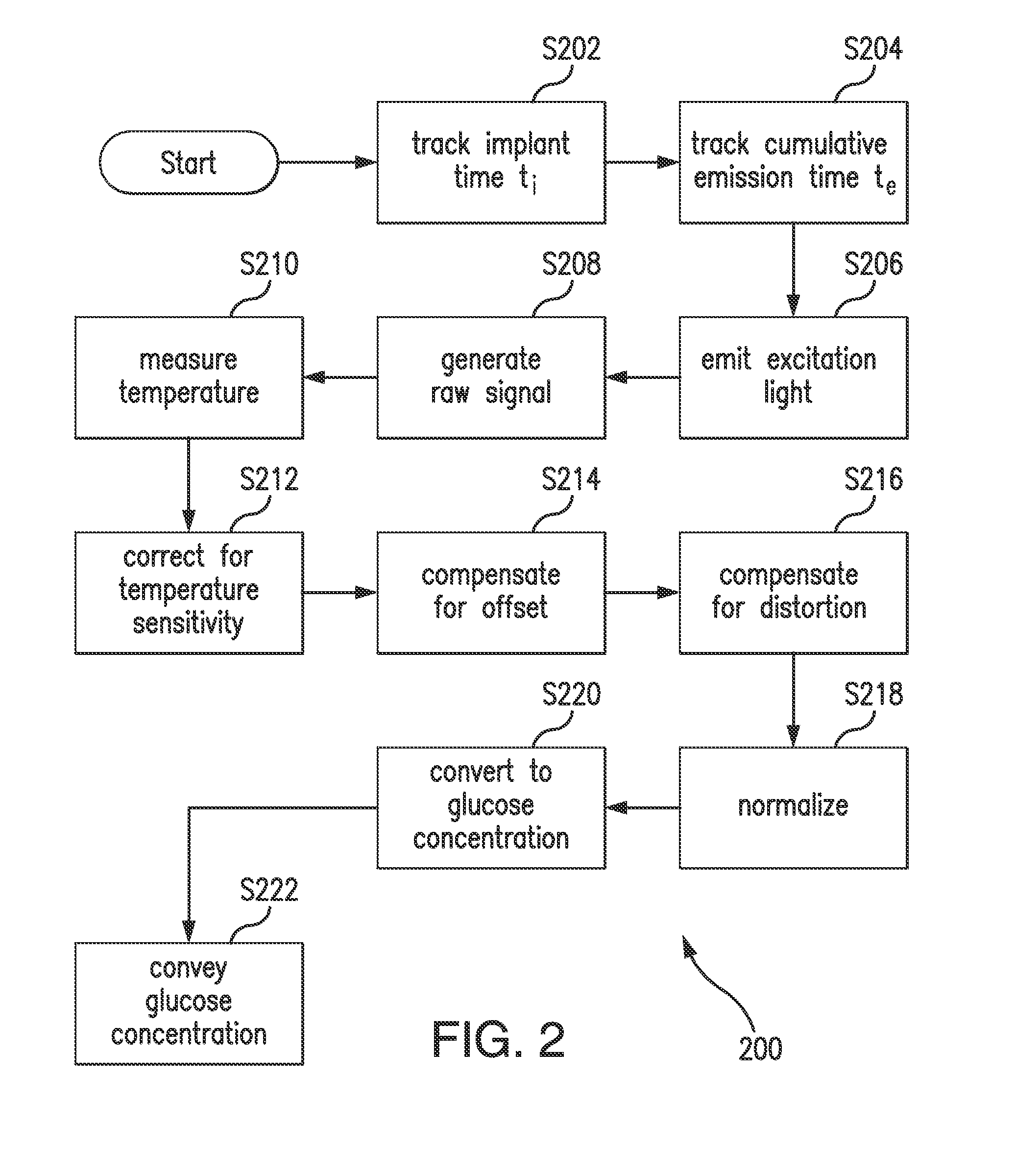
Methods, sensors, and systems for determining a concentration of glucose in a medium of a living animal are disclosed. Determining the glucose concentration may involve emitting excitation light from a light source to indicator molecules, generating a raw signal indicative of the amount of light received by a photodetector, purifying and normalizing the raw signal, and converting the normalized signal to a glucose concentration. The purification may involve removing noise (e.g., offset and / or distortion) from the raw signal. The purification and normalization may involve tracking the cumulative emission time that the light source has emitted the excitation light and tracking the implant time that has elapsed since the optical sensor was implanted. The purification and normalization may involve measuring the temperature of the sensor. The purification, normalization, and conversion may involve using parameters determined during manufacturing, in vitro testing, and / or in vivo testing.

Description

CROSS-REFERENCE TO RELATED APPLICATION[0001]The present application is a continuation-in-part of U.S. patent application Ser. No. 13 / 853,095, filed on Mar. 29, 2013, which is incorporated by reference in its entirety and claims the benefit of priority to U.S. Provisional Application Ser. No. 61 / 617,414, filed on Mar. 29, 2012, which is also incorporated herein by reference in its entirety.BACKGROUND[0002]1. Field of Invention[0003]The present invention relates generally to determining a concentration of glucose in interstitial fluid of a living animal using an optical sensor implanted in the living animal. Specifically, the present invention relates to purification of a raw signal including a glucose-modulated component to remove noise (e.g., offset and / or distortion) and converting the processed signal to a glucose concentration.[0004]2. Discussion of the Background[0005]A sensor may be implanted within a living animal (e.g., a human) used to measure the concentration of glucose in...

Claims


Application Information

Patent Timeline
Patent Type & Authority Applications(United States)
IPC IPC(8): A61B5/145A61B5/1459
CPCA61B5/14532A61B5/1459A61B5/14556A61B5/7203
Inventor COLVIN, JR., ARTHUR E.WANG, XIAOLINMDINGI, COLLEENDEHENNIS, ANDREW
Owner SENSEONICS INC
Learn More