System for testing error detection circuits

a technology for error detection circuits and circuits, applied in error detection/correction, detecting faulty computer hardware, instruments, etc., can solve the problems of high manufacturing cost and difficulty in detecting any malfunction during the operational life of error detection circuits

Active Publication Date: 2014-01-16
NXP USA INC
View PDF10 Cites 32 Cited by
  • Summary
  • Abstract
  • Description
  • Claims
  • Application Information

AI Technical Summary

Problems solved by technology

The above schemes for testing error detection circuits require additional testing equipment (i.e., the microcontroller and the robotic arm mechanism), which entails high manufacturing costs.
Additionally,

Method used


Image

  • System for testing error detection circuits
  • System for testing error detection circuits
  • System for testing error detection circuits

Examples


Embodiment Construction

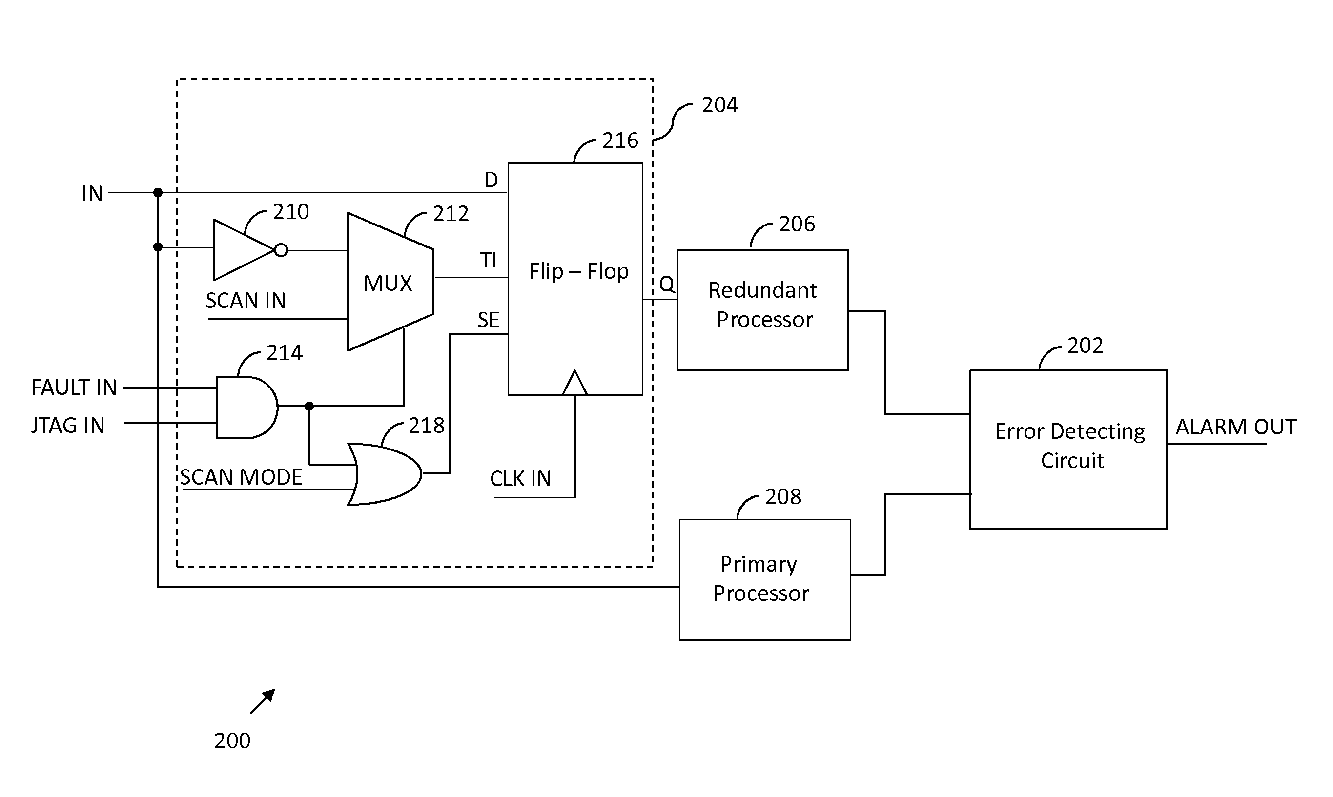
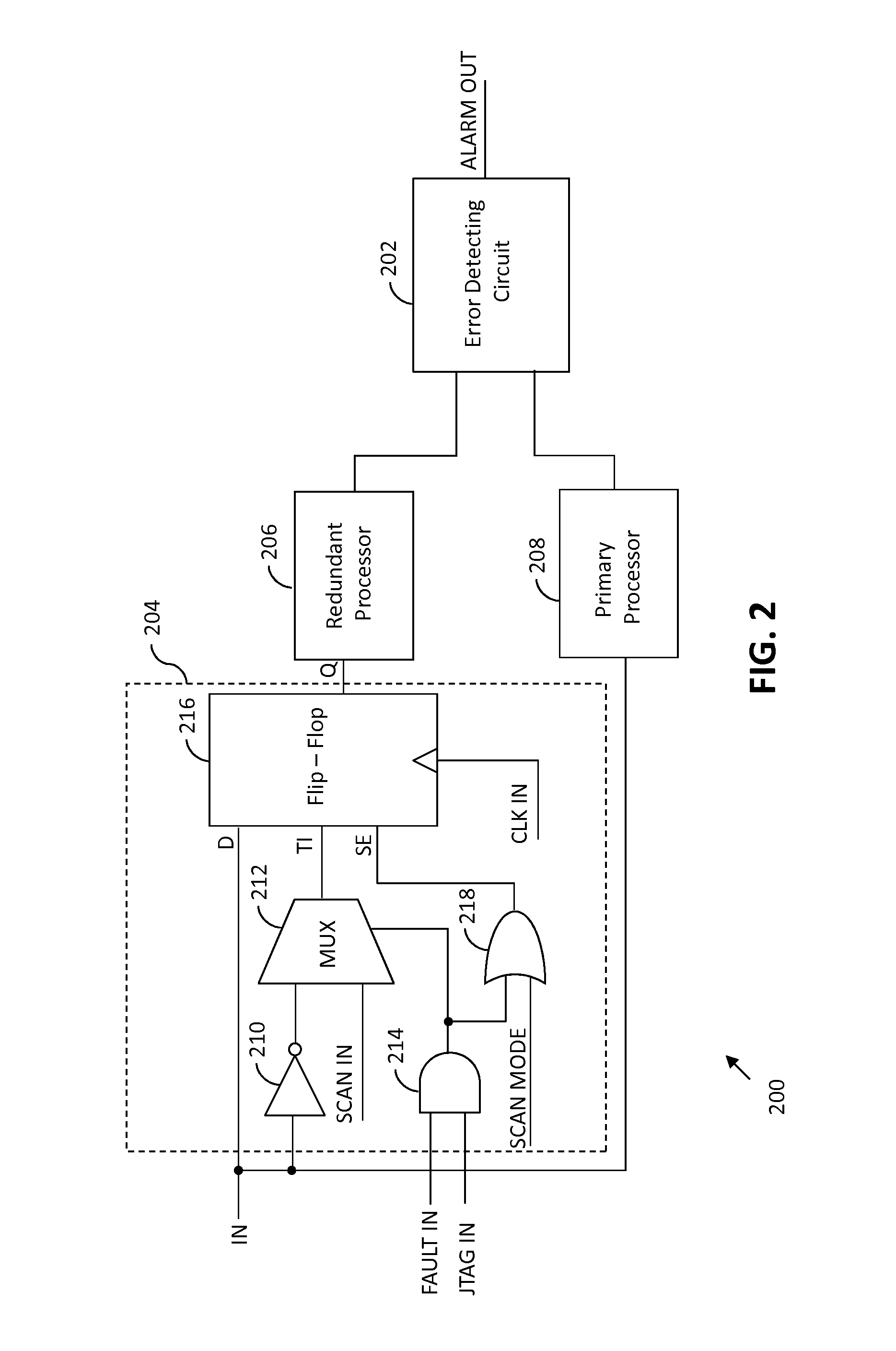
[0010]The detailed description of the appended drawings is intended as a description of the currently preferred embodiments of the present invention, and is not intended to represent the only form in which the present invention may be practiced. It is to be understood that the same or equivalent functions may be accomplished by different embodiments that are intended to be encompassed within the spirit and scope of the present invention. In the description hereinafter, the term multiplexer has been abbreviated as mux.

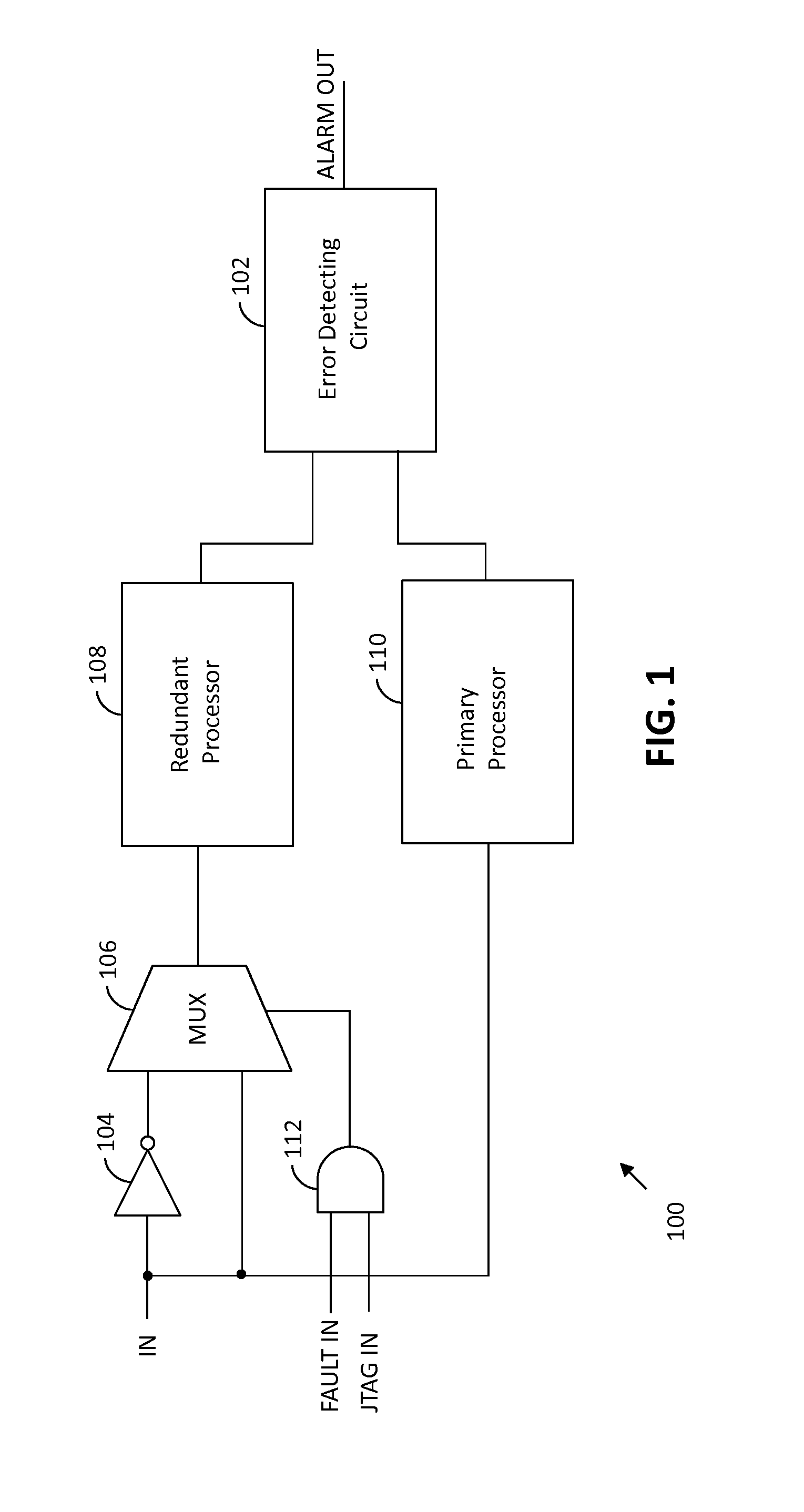
[0011]In an embodiment of the present invention, a system for testing an error detection circuit by injecting a fault therein is provided. The error detection circuit receives first and second output signals generated by first and second processors, respectively, and detects errors therein. The system includes a NOT gate for receiving an input signal and generating an inverted input signal, an AND gate for receiving test mode and fault injection mode signals and generat...


PUM


Abstract

A system for testing an error detection circuit includes a fault injection unit for operating the error detection circuit in a fault injection mode. A fault is inserted in either of a primary or a redundant processor. Output signals generated by the primary and redundant processors are compared and checked for a mismatch and the error detection circuit outputs a test signal based on the comparison result.

Description

BACKGROUND OF THE INVENTION[0001]The present invention relates generally to testing electronic circuits, and, more particularly, to a system for testing error detection circuits.[0002]In recent years, advancements in the field of technology have resulted in electrical and electronic systems becoming an integral part of automobiles. Automobiles are equipped with microcontrollers (also known as engine control units or ECUs) that control many various functions of the automobile. An ECU receives inputs from sensors mounted on different parts of the automobile. For example, a crankshaft position sensor transmits the angular position of the crankshaft to the ECU, based on which the ECU controls fuel injection and spark plug firing. Various other sensors are provided for sensing pressure, speed, and temperature of different automobile parts, which allow the ECU to control other functions of the automobile.[0003]Automotive ECUs are required to comply with stringent safety regulations that r...

Claims


Application Information

Patent Timeline
IPC IPC(8): G01R31/3177G06F11/25
CPCG01R31/31703G01R31/318544G06F11/2215G06F21/556
Inventor JINDAL, AMITSINGH, NITIN
Owner NXP USA INC
Why Eureka
Try Eureka