Valve-Controllable Urinal Drain Line and Plumbing Component Rinse Management System for Very Low Water and/or Non-Water Use Urinals

a technology of valve control and urinal, which is applied in the field of valve controllable urinal drain line and plumbing component rinse management system, can solve the problems of 800 million people worldwide who will not have a sufficient supply of water, significant decreases in the amount of water needed to flush toilets and urinals, and do not represent the best of what is attainable in urinal related water conservation. , to achieve the effect of preventing backflow or upswelling of valve controllabl

Inactive Publication Date: 2014-01-23
METCALF DARRELL +1
View PDF13 Cites 28 Cited by
  • Summary
  • Abstract
  • Description
  • Claims
  • Application Information

AI Technical Summary

Benefits of technology

[0010]The objects of the present invention are achieved through a valve-controllable urinal drain line and plumbing component rinse management system configured for periodically rinsing, flushing or purging non-water urinal drainage plumbing or ultra high efficiency urinal (ultra-HEU) drainage plumbing, or both, and doing so in a water and energy conserving manner. In one of the embodiments, the system incorporates one or more non-water or ultra high efficiency urinals, or both, e.g., wall-mounted or otherwise configured for use by a user, each having a urinal drain pipe or conduit preferably configured to pass liquid in a single or urinal-exiting direction e.g., by incorporating a on

Problems solved by technology

It is projected that over 800 million people worldwide will not have a sufficient supply of water.
For example, in recent years water-conserving efforts made by manufacturers of plumbing fixtures have lead to significant decreases in the amount of water needed to flush toilets and urinals.
While such improvements have come relatively quickly and have contributed to significant reduction in water usage, they do not represent the best in what is attainable in urinal related water conservation.
For example non-water urinals, initially thought to be an ideal solution to reducing urinal water use, have been

Method used


Image

  • Valve-Controllable Urinal Drain Line and Plumbing Component Rinse Management System for Very Low Water and/or Non-Water Use Urinals
  • Valve-Controllable Urinal Drain Line and Plumbing Component Rinse Management System for Very Low Water and/or Non-Water Use Urinals
  • Valve-Controllable Urinal Drain Line and Plumbing Component Rinse Management System for Very Low Water and/or Non-Water Use Urinals

Examples


Embodiment Construction

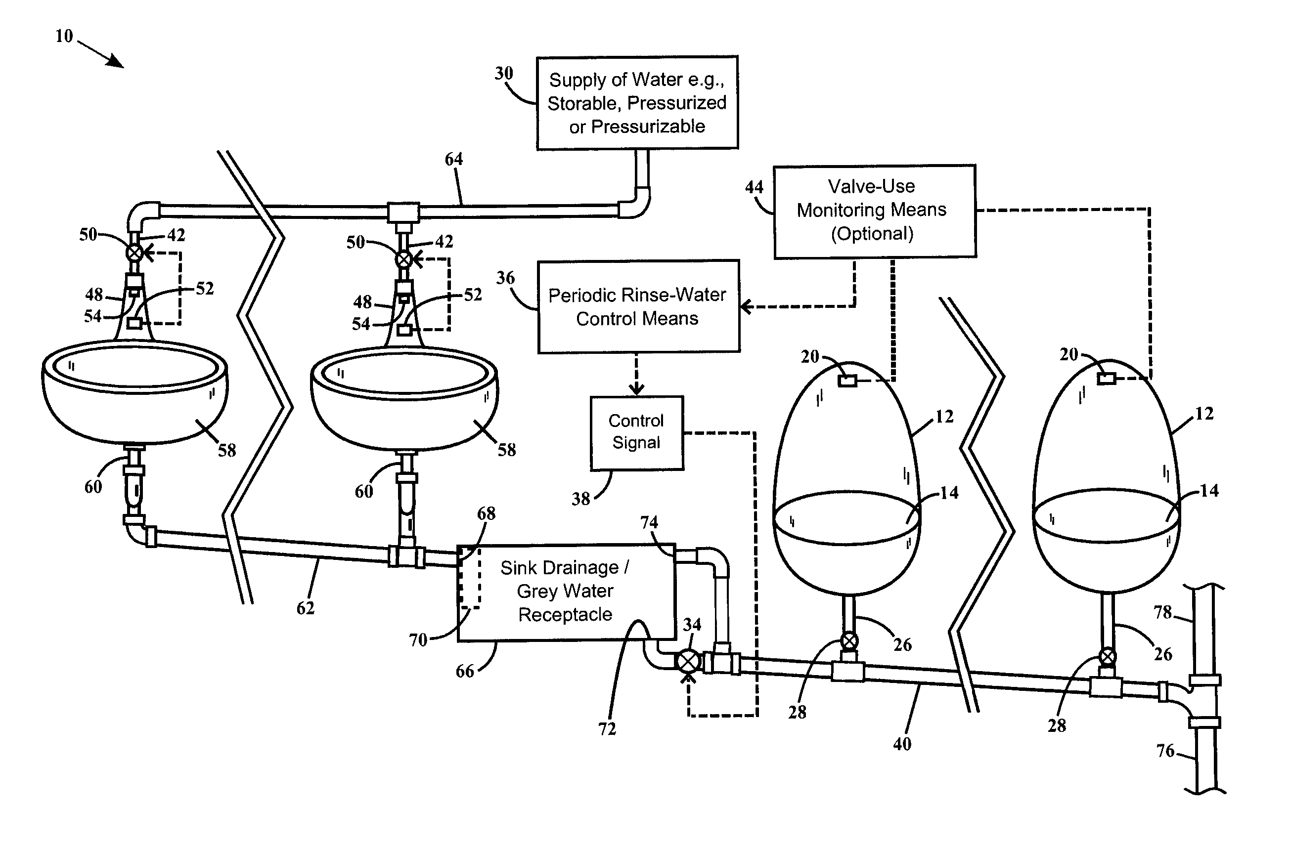
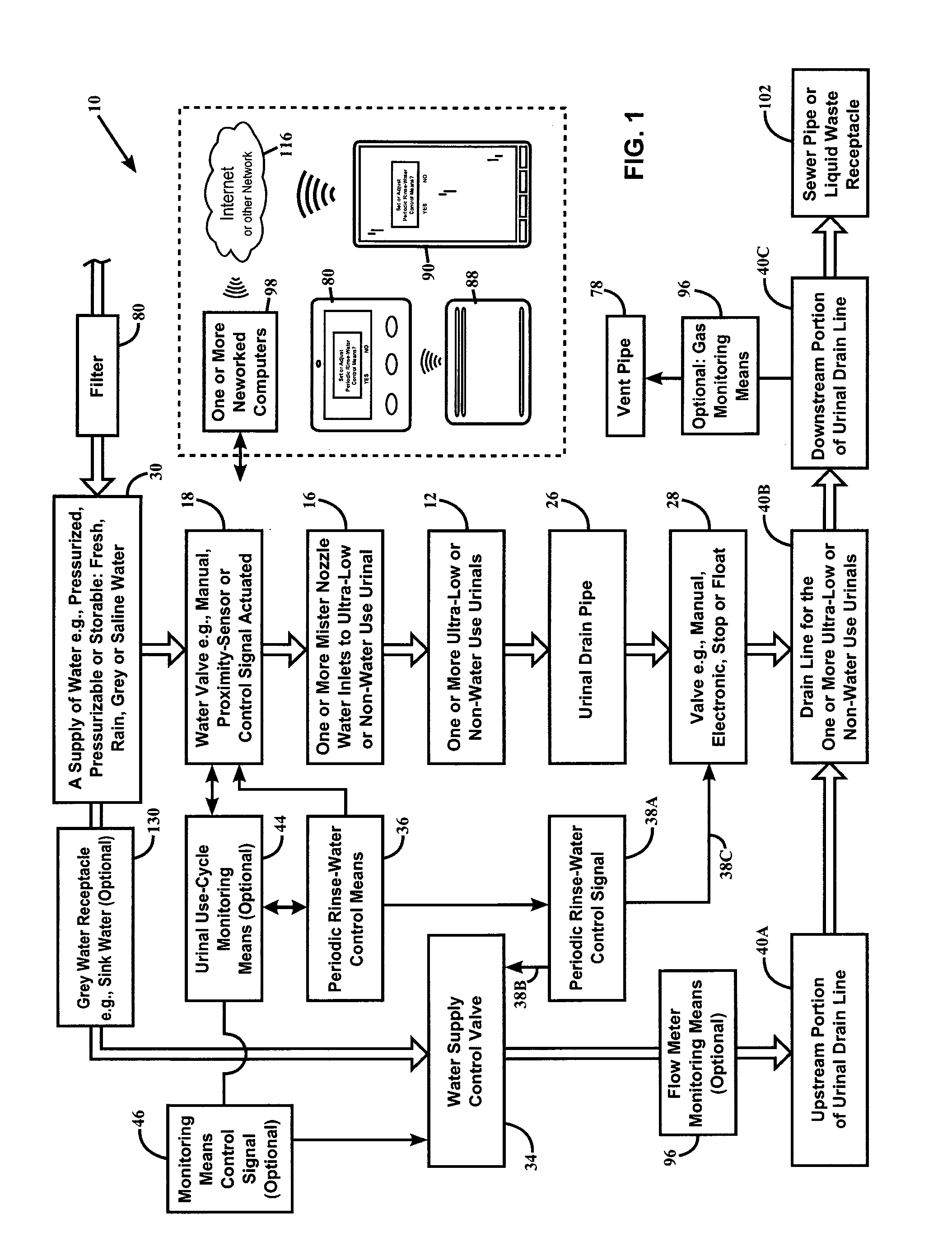
[0024]In reference to FIG. 1, a representation of one of the preferred embodiments of the system (and one or more optional components) is depicted in a block diagram illustrating the managing of a flow of water as employed by the water and energy saving and plumbing component rinsing system (the flow of water is diagrammatically depicted by the broader parallel-lined arrows). For example, a flow of water in the system preferably passes through a filter 80 or line filter, and includes a supply of water 30 which is configured periodically controllable by a water supply control valve 34. Optionally or additionally the system also provides a controlling of some of the supply of water 30 with a water valve 18 e.g., when the system includes one or more ultra-low water use urinals or non-water urinals 12 (or both) configured with a urinal receptacle that can be advantageously rinsed at periodic intervals, other than when an individual is employing a urinal during a typical use-cycle. As de...


PUM


Abstract

A water-conserving system equipped to periodically rinse ultra high-efficiency urinal drainage plumbing of corrosive waste liquid and reduce associated gaseous odor is provided. A valve-controllable rinse-cycle supply of water is provided which can selectively be directed into a single drainage conduit which receives waste water from one or more ultra high-efficiency urinals. The system provides embodiments having mechanical valves, or electro-mechanical valves configured responsive to control-signals provided from one or more electronic components, or one or more types of microprocessor-enabled devices, networked devices or computer apparatus.

Description

CROSS-REFERENCE TO RELATED APPLICATION[0001]This application is a non-provisional application which relies on U.S. provisional patent application Ser. No. 61 / 508,610 filed on Jul. 16, 2011, the disclosure of which is hereby incorporated by reference as if fully set forth herein.FIELD OF THE INVENTION[0002]The present invention pertains generally to the field of water and energy conserving plumbing products, fixtures and systems. More specifically the invention relates to a valve-controllable urinal drain line and plumbing component rinse management system equipped to periodically convey a controllable supply of water or water solution (e.g., fresh, saline, alkali-enriched, rain water, grey water or water with one or more cleaning agents) as needed for rinsing the plumbing drainage line (and optionally one or more other plumbing components) of systems equipped with non-water urinals using no flush water per use-cycle, and / or ultra-high efficiency urinals (‘Ultra-HEU’) using less than...

Claims


Application Information

Patent Timeline
IPC IPC(8): E03D13/00
CPCE03D13/007E03D5/10
Inventor METCALF, DARRELLTICHENOR, CLYDE LEROY
Owner METCALF DARRELL
Why Eureka
Try Eureka