Pneumatic tire

a pneumatic tire and tire technology, applied in the field of pneumatic tires, can solve the problems of reduced high-speed durability of tires, low thermal conductivity of materials used for noise dampers, and reduced tire productivity, so as to reduce cavity resonance, improve the effect of maintenance efficiency and high-speed durability

Inactive Publication Date: 2014-01-23
MICHELIN & CO CIE GEN DES ESTAB MICHELIN +1
View PDF3 Cites 12 Cited by
  • Summary
  • Abstract
  • Description
  • Claims
  • Application Information

AI Technical Summary

Benefits of technology

[0037]According to the present invention constructed in this way sound waves from the vibration of air introduced into the continuous groove permeate into / are reflected by the continuous ribbon in an irregular fashion, so it is possible to ensure high-speed durability and to maintain productivity more effectively while a reduction in cavity resonance can be envisaged.
[0038]The pneumatic tire according to the present invention makes it possible to maintain high-speed durability and productivity while reducing cavity resonance.

Problems solved by technology

However, the material which is generally used for the noise damper has low thermal conductivity, so there is a problem with the technology described in Patent Documents 1 and 2 in that the high-speed durability of the tire is reduced when the noise damper covers a wide range of the order of 40% of the tire internal surface in order to reduce cavity resonance.
Furthermore, there is a problem with the technology described in Patent Document 3 in that the process to fit the noise dampers to the tire internal surface is complex because multiple noise dampers have to be introduced, so the productivity of this kind of tire is reduced.
On the other hand, if the thickness E of the continuous ribbon is greater than 200% of the width W of the continuous ribbon, the sound-suppression effect afforded by the continuous ribbon plateaus, and therefore this adversely affects the cost and weight of the tire.

Method used


Image

  • Pneumatic tire
  • Pneumatic tire
  • Pneumatic tire

Examples


Embodiment Construction

[0047]Preferred modes of embodiment of the present invention will be described below with reference to the figures.

[0048]A pneumatic tire according to a first mode of embodiment of the present invention will be described first of all with reference to FIGS. 1 and 2.

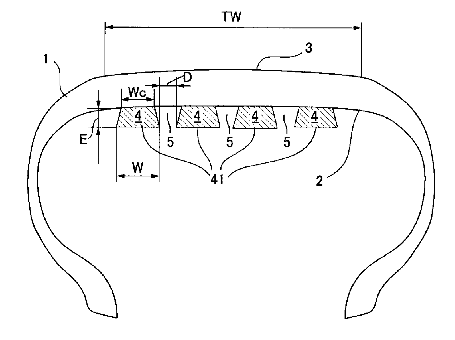
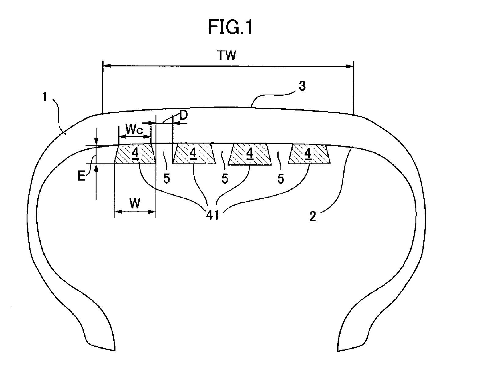
[0049]FIG. 1 is a schematic view in cross section in the radial direction of a pneumatic tire provided with a noise damper according to a first mode of embodiment of the present invention, and FIG. 2 is a schematic view of the internal surface of a pneumatic tire provided with a noise damper according to a first mode of embodiment of the present invention. In FIG. 2 the circumferential direction of the tire is denoted by YY′, and the axial direction of the tire is denoted by XX′.

[0050]First of all, as shown in FIG. 1, the symbol 1 denotes a pneumatic tire 1 which is provided with a noise damper 4 according to a first mode of embodiment of the present invention. The noise damper 4 serves to reduce cavity resonance, and as ...


PUM


Abstract

A pneumatic tire provided with a noise damper in the tire cavity, which can maintain high-speed durability and productivity while also reducing cavity resonance, comprising a tread having a width TW in contact with the ground during travel, in which a noise damper made of a sound-absorbing material is attached to the tire internal surface in order to reduce cavity resonance, wherein the noise damper is at least one continuous ribbon made of a sound-absorbing material and having a width W and a thickness E, which is fixed over an attachment width Wc to the tire internal surface over a range of at least 30% of the inside of the tread in the radial direction, the start end and terminal end which are the two ends of the continuous ribbon are disposed in such a way as to be offset from each other in the axial direction, and the continuous ribbon forms, together with the tire internal surface, a continuous groove having a groove width D which is at least equal to 10% of the width W of the continuous ribbon.

Description

BACKGROUND[0001]1. Technical Field[0002]The present invention relates to a pneumatic tire, and specifically the invention relates to a pneumatic tire provided with a noise damper for suppressing cavity resonance produced in a tire cavity.[0003]2. Description of Related Art[0004]Resonant vibration (cavity resonance) in a tire cavity is generated by the vibration of air enclosed in the tire cavity. The air in the tire cavity is generally excited by deformation of the tire tread part and sidewall part as the tire travels, and air enclosed in the annular cavity acts as an air column when this air is excited.[0005]Sound waves which are excited in the tire cavity are transmitted inside the vehicle compartment as a solid-borne sound which spreads through the wheels, suspension and motor vehicle body, and is felt by vehicle passengers as disagreeable low-frequency noise.[0006]Introducing a noise damper into the tire cavity is known as an effective means for reducing the cavity resonance, an...

Claims


Application Information

Patent Timeline
Patent Type & Authority Applications(United States)
IPC IPC(8): B60C5/00
CPCB60C19/002B29D30/0061Y10T152/10495
Inventor GREVERIE, LUDOVICPARFONDRY, ALAINDELFINO, ANTONIOFOMBELLE, DAMIEN
Owner MICHELIN & CO CIE GEN DES ESTAB MICHELIN
Why Eureka
Try Eureka