

Hydrocarbon Viscosity Reduction Method
a technology of viscosity reduction and hydrocarbons, applied in the field of hydrocarbon processing, can solve the problems of increasing the viscosity of the base solvent oil, not being able to completely precipitate asphaltene from solution, and being energy-intensive, so as to reduce the amount of diluent, increase energy efficiency, and reduce the viscosity of heavy oils
- Summary
- Abstract
- Description
- Claims
- Application Information
AI Technical Summary
Benefits of technology
Problems solved by technology
Method used
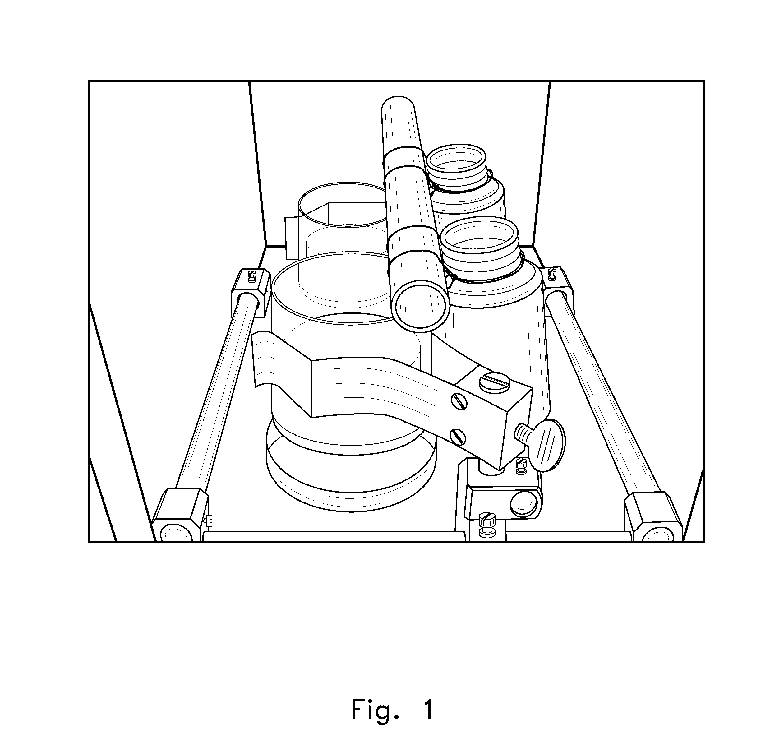
Image

Examples
Embodiment Construction
[0031]As mentioned earlier, the present invention includes a variety of aspects, which may be combined in different ways. The following descriptions are provided to list elements and describe some of the embodiments of the present invention. These elements are listed with initial embodiments, however it should be understood that they may be combined in any manner and in any number to create additional embodiments. The variously described examples and preferred embodiments should not be construed to limit the present invention to only the explicitly described systems, techniques, and applications. Further, this description should be understood to support and encompass descriptions and claims of all the various embodiments, systems, techniques, methods, devices, and applications with any number of the disclosed elements, with each element alone, and also with any and all various permutations and combinations of all elements in this or any subsequent application.
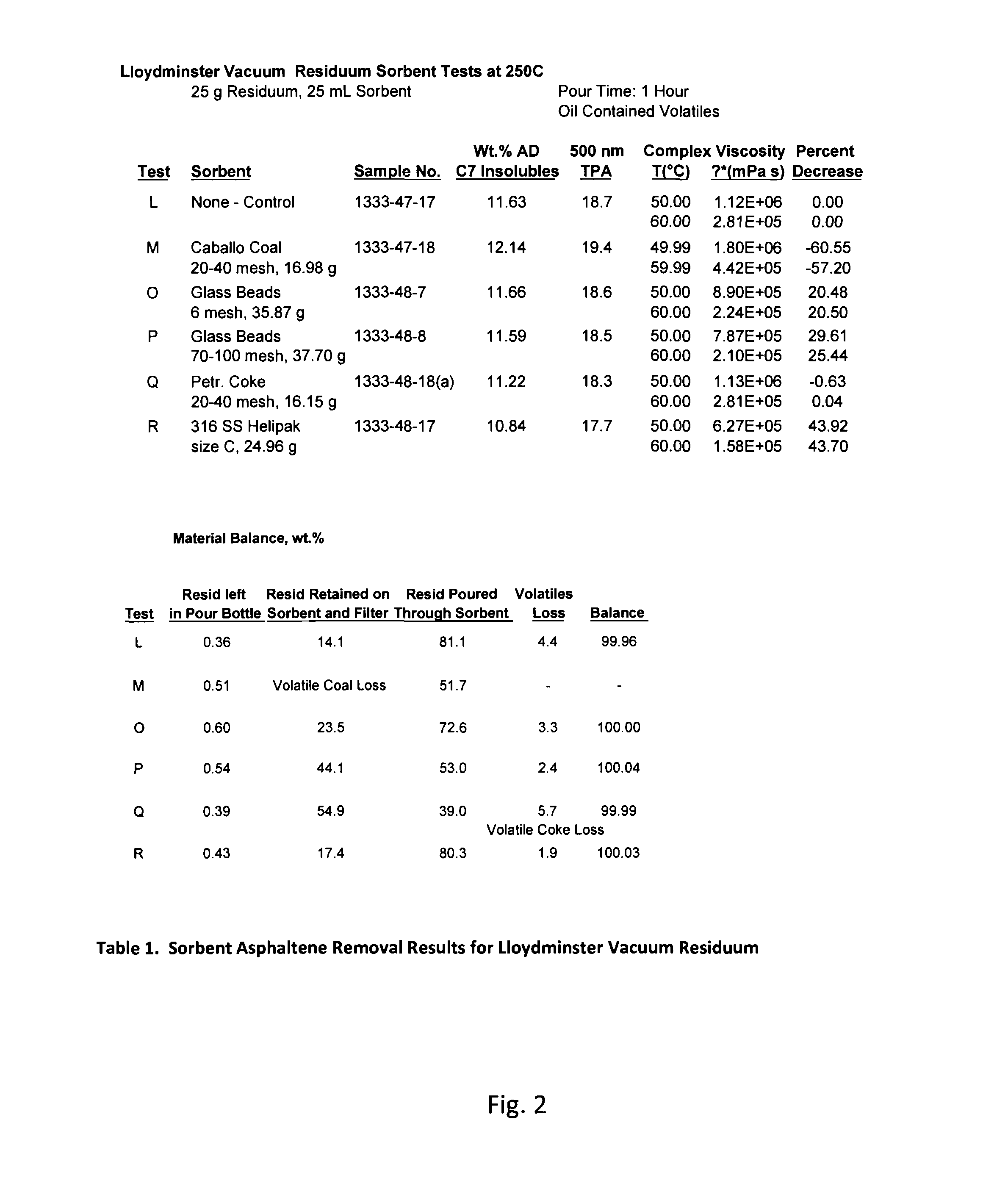
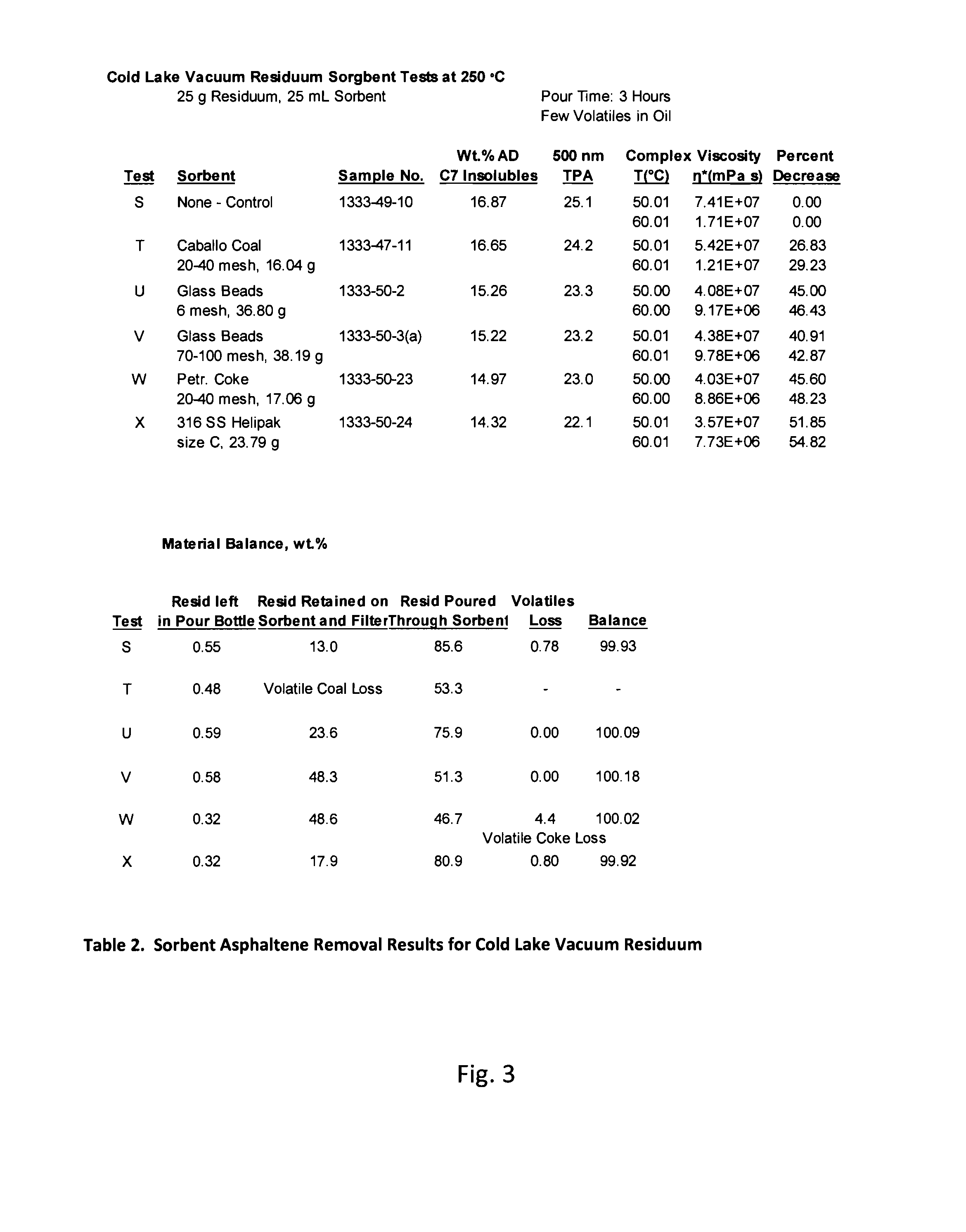
Vacuu...
PUM
| Property | Measurement | Unit |
|---|---|---|
| temperature | aaaaa | aaaaa |
| temperature | aaaaa | aaaaa |
| temperature | aaaaa | aaaaa |
Abstract
Description
Claims
Application Information