
Heating Appliance

Active Publication Date: 2014-01-23
SPECTRUM BRANDS INC
View PDF10 Cites 5 Cited by
  • Summary
  • Abstract
  • Description
  • Claims
  • Application Information

AI Technical Summary

Benefits of technology

The patent text describes a heating appliance with a heating element and a heat distribution member. The heating element is designed to have a uniform temperature along its length during heating. The heat distribution member is placed between the heating element and the rack, and it has a pattern of apertures that taper in response to the temperature increase of the heating element. This pattern of apertures is designed to ensure even distribution of heat and improved cooking performance. The technical effect of the patent text is to provide a heating appliance with improved heat distribution to ensure even cooking and a superior cooking experience.

Problems solved by technology

However, in many of these heating appliances, the distribution members do not achieve the desired results.

Method used


Image

  • Heating Appliance
  • Heating Appliance
  • Heating Appliance

Examples


Embodiment Construction

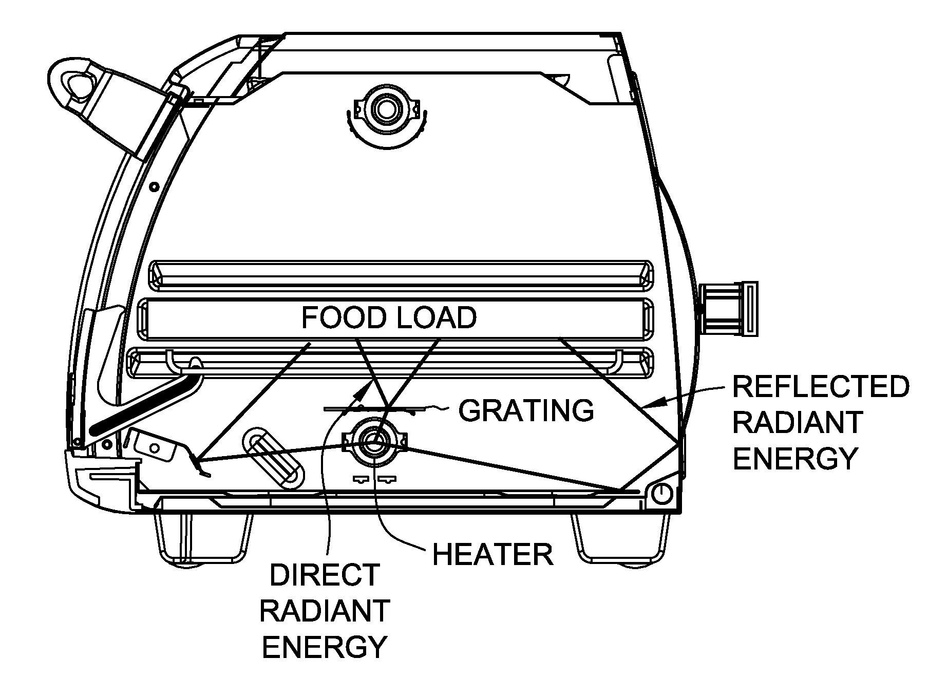
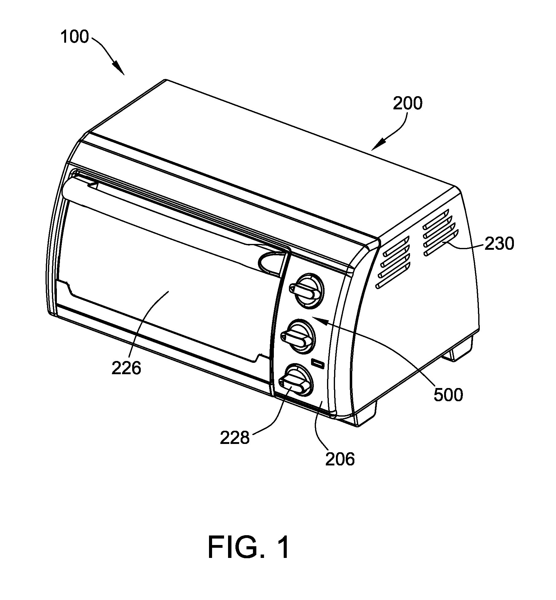
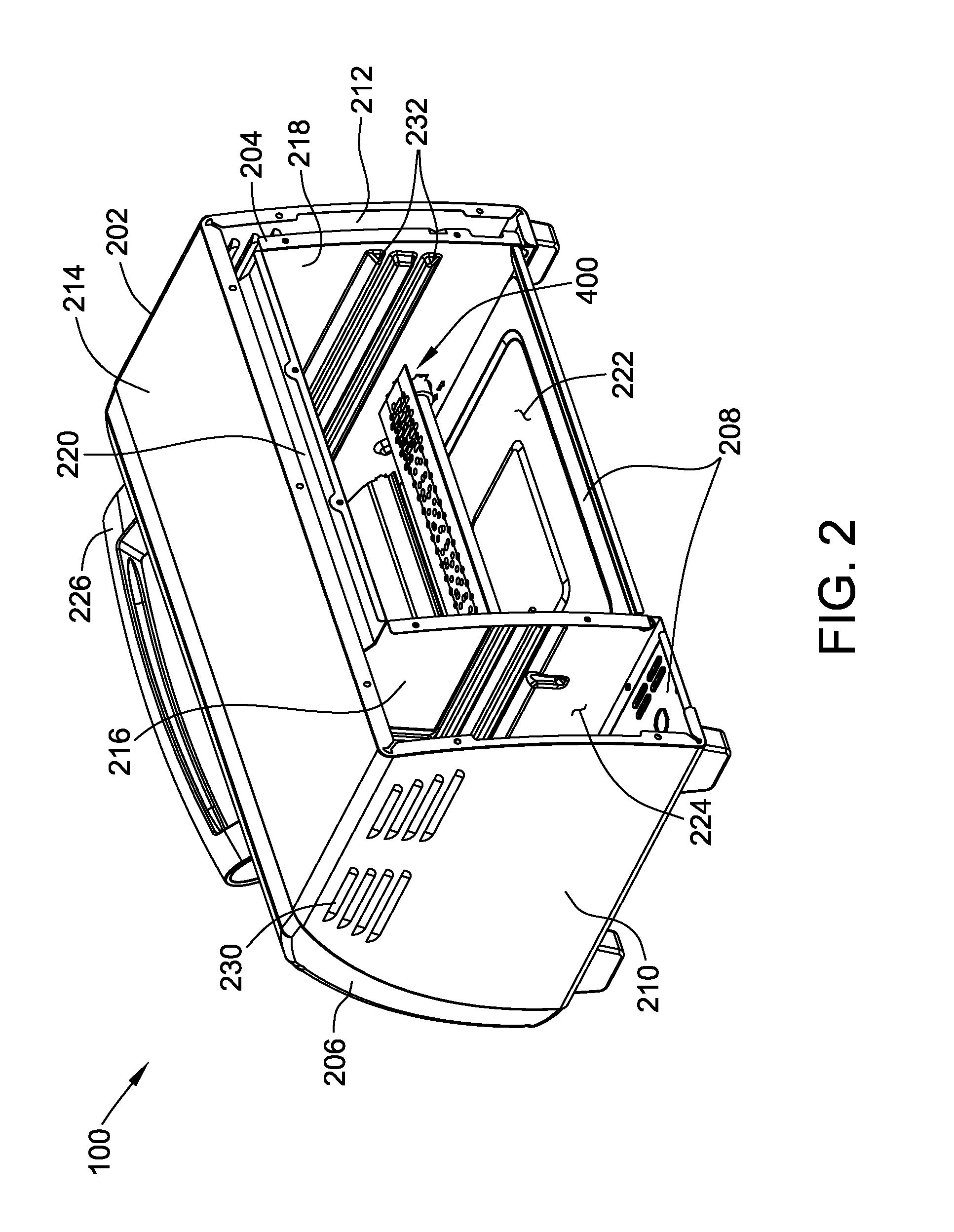
[0032]Referring now to the drawings, and in particular to FIGS. 1-7, a heating appliance (e.g., a toaster oven) according to one embodiment is indicated generally by the reference numeral 100. The illustrated heating appliance 100 comprises a housing (indicated generally at 200), an upper heating assembly (indicated generally at 300 in FIG. 3), a lower heating assembly (indicated generally at 400 in FIG. 2), and a heat control system (indicated generally at 500).

[0033]The illustrated housing 200 has an exterior frame 202, an interior frame 204, a front panel assembly 206, a rear panel assembly (not shown), and a bottom panel assembly 208. The exterior frame 202, the interior frame 204, the front panel assembly 206, the rear panel assembly, and the bottom panel assembly 208 may be fabricated using any material suitable for the associated functions described herein.

[0034]The exterior frame 202 has a first exterior side panel 210, a second exterior side panel 212, and an exterior top p...


PUM


Abstract

A heating appliance generally includes a housing defining a food product compartment, and a rack configured to support a food product within the food product compartment. The heating appliance further includes a heating assembly disposed within the food product compartment. The heating assembly includes a heating element having a length, wherein the heating element is configured to have a temperature increase along the length during heating. The heating assembly further includes a heat distribution member disposed between the heating element and the rack, wherein the heat distribution member includes a pattern of apertures that tapers in accordance with the temperature increase of the heating element.

Description

CROSS-REFERENCE TO RELATED APPLICATIONS[0001]This application claims the benefit of U.S. Provisional Application No. 61 / 620,103 filed Apr. 4, 2012, which is incorporated herein in its entirety.BACKGROUND[0002]The present invention relates generally to appliances and, more particularly, to an appliance for heating a food product.[0003]Many conventional heating appliances such as toaster ovens have a heating device and a food rack mounted within a housing for heating a food product (e.g., bread) placed on the rack using the heating device. A door provides access to the interior of the appliance for placing the food product on the rack, and a user interface provides control over the heat emitted by the heating device (e.g., control over the temperature and duration of heating).[0004]In at least some heating appliances, a heat distribution member may be situated between the heating device and the rack to facilitate evenly distributing heat incidence over the food product. However, in ma...

Claims


Application Information

Patent Timeline
IPC IPC(8): A47J37/06A47J37/08
CPCA47J37/0635A47J37/0807A47J37/0652F24C1/10A47J37/0611
Inventor SMITH, JACOB DANIELNERNBERGER, KROY EVERETTKLOCK, CASEY AARONPATULLO, JAMES RAYMONDKREBS, JOSEPH VALDONEVERETT, JR., DAVID W.POIDL, MILAN
Owner SPECTRUM BRANDS INC
Features
  • Generate Ideas
  • Intellectual Property
  • Life Sciences
  • Materials
  • Tech Scout
  • Unparalleled Data Quality
  • Higher Quality Content
  • 60% Fewer Hallucinations
Learn More