
Method for monitoring the state of a fill level measuring device operating according to the radar principle

Active Publication Date: 2014-01-23
KROHNE SA
View PDF3 Cites 4 Cited by
  • Summary
  • Abstract
  • Description
  • Claims
  • Application Information

AI Technical Summary

Benefits of technology

The present invention provides a method and device for measuring the level of a medium using radar principles. The device has a simplified design for monitoring the seal facing the medium, which makes it easier to detect any leaks or process modifications. The interior space is filled with either dry air or a vacuum, and a ceramic wall section is used which has low permittivity and can handle various corrosive or high temperature conditions. The device also includes at least one electrical conductor arranged in the ceramic wall section. Overall, the invention has a simple and cost-effective construction.

Problems solved by technology

Such a procedure is questionable for dangerous and / or polluting substances or unacceptable in hygienic applications in the food and pharmaceutical industries.
However, this configuration is complex.

Method used


Image

  • Method for monitoring the state of a fill level measuring device operating according to the radar principle
  • Method for monitoring the state of a fill level measuring device operating according to the radar principle
  • Method for monitoring the state of a fill level measuring device operating according to the radar principle

Examples


Embodiment Construction

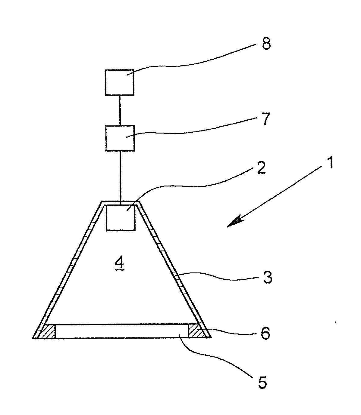
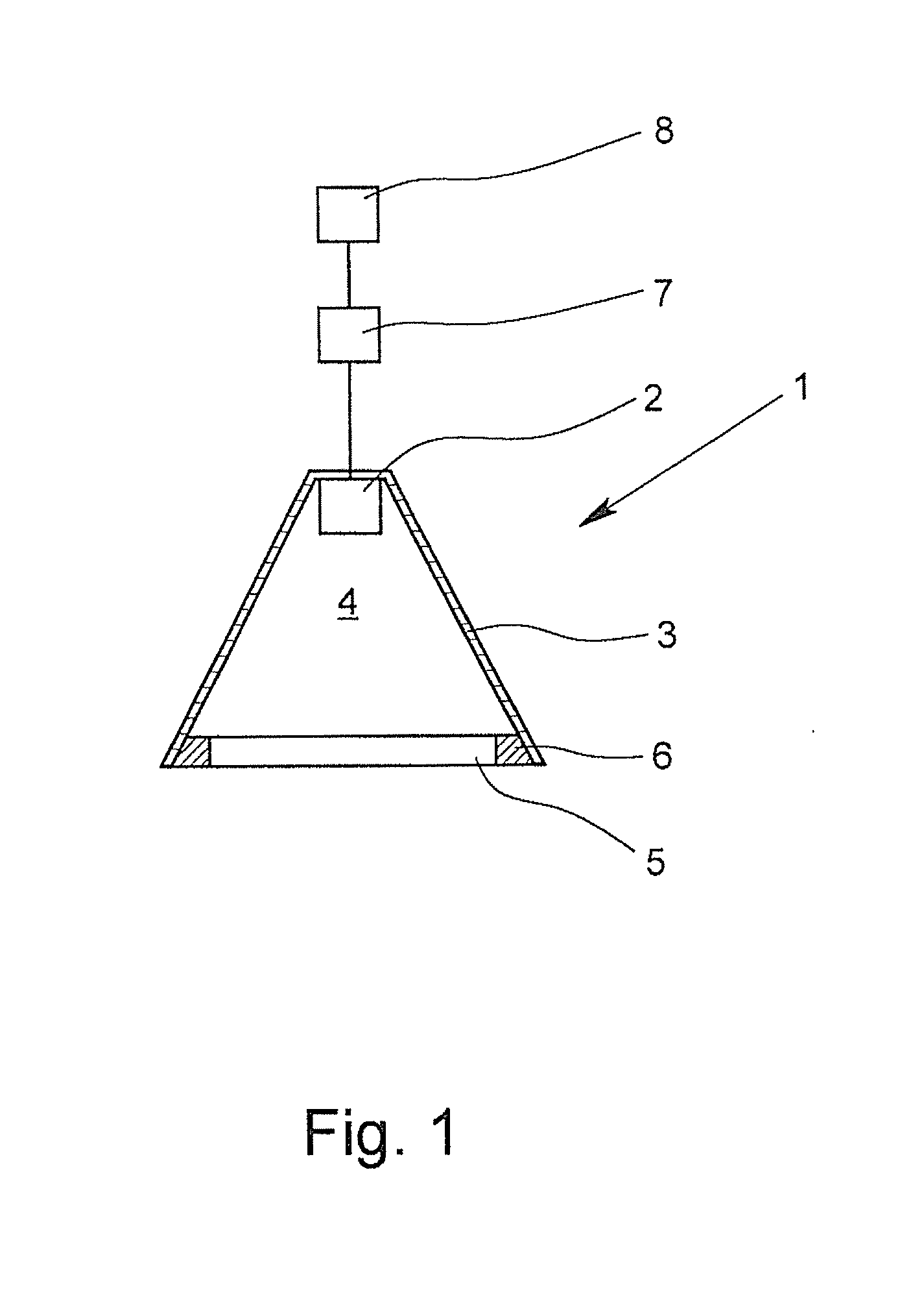
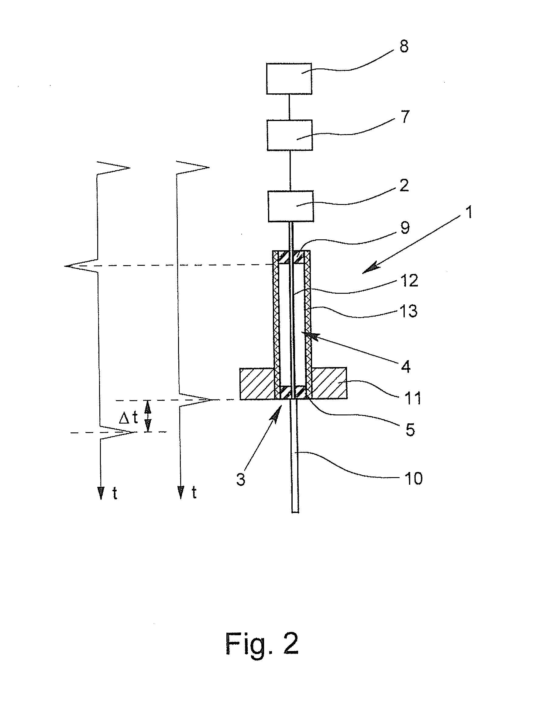
[0021]FIG. 1 shows a fill level measuring device 1 according to the invention. Electromagnetic signals are generated by the transceiver unit 2, and in particular, received again after reflection on the surface of the—not shown here—medium, whose fill level is to be determined. These are, in particular, microwave signals. An antenna 3 is used for guiding, emitting and receiving the signals, the antenna 3 being designed as a horn antenna in the illustrated embodiment and having an interior space 4 in its recess, which is limited in the direction of the medium—not shown here—by a wall section 5. The wall section 5 is comprised, in particular, of a so-called cermet, i.e., a composite material of a ceramic and a metal. The (here) circular wall section 5 is surrounded by a metal ring 6, which is used to connect to the antenna 3. The interior space 4, which is limited on one side by the transceiver unit 2, is filled with air in the embodiment shown.

[0022]The control unit 7 is used to contr...


PUM


Abstract

A method for monitoring the state of a fill level measuring device (1) operating according to the radar principle and such a fill level measuring device, wherein the fill level measuring device (1) has at least one transceiver unit (2) for transmitting and receiving electromagnetic signals, and at least one antenna (3) for guiding, radiating and receiving electromagnetic signals. The antenna (3) has at least one interior space (4), and wherein the antenna (3) has a transmission characteristic with regard to the transmission of electromagnetic signals. Electromagnetic signals are emitted or directed at least partially in the direction of a wall section (5) of the interior space (4) of the antenna (3), the received electromagnetic signals are evaluated with respect to the transmission characteristic of the antenna (3), and the result of the evaluation is compared to at least one stored reference value.

Description

BACKGROUND OF THE INVENTION[0001]1. Field of the Invention[0002]The invention relates to a method for monitoring the state of a fill level measuring device operating according to the radar principle, wherein the fill level measuring device comprises at least one transceiver unit for transmitting and receiving electromagnetic signals, wherein the fill level measuring device has at least one antenna for guiding, radiating and receiving electromagnetic signals, wherein the antenna has at least one interior space, and wherein the antenna is characterized by a transmission characteristic with regard to the transmission of electromagnetic signals. Furthermore, the invention relates to a fill level measuring device operating according to the radar principle, having at least one transceiver unit for transmitting and receiving electromagnetic signals and at least one antenna for guiding, radiating and receiving electromagnetic signals, wherein the antenna has at least one interior space, and...

Claims


Application Information

Patent Timeline
IPC IPC(8): G01S13/08G01S7/40
CPCG01S13/08G01S7/40G01F23/284G01F23/804
Inventor PICHOT, VINCENT
Owner KROHNE SA
Learn More