
Pose monitoring method suitable for floating support installation jacking plane and butt joint plane

A technology of docking planes and plane equations, applied in the direction of optical devices, measuring devices, special data processing applications, etc., to achieve the effects of improving monitoring accuracy and environmental anti-interference, simple calculation methods, and high monitoring accuracy

Pending Publication Date: 2021-07-16
TIANJIN UNIV
View PDF0 Cites 0 Cited by
  • Summary
  • Abstract
  • Description
  • Claims
  • Application Information

AI Technical Summary

Problems solved by technology

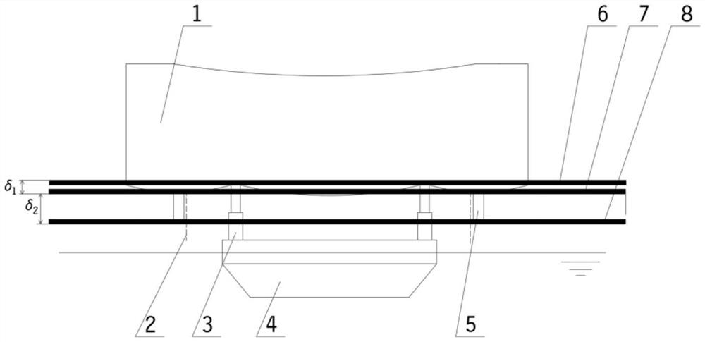
[0004] The advantages of the present invention: the laser ranging sensor is used as the main monitoring instrument to improve monitoring accuracy and environmental anti-interference; get rid of the traditional idea of ​​only monitoring the bottom surface of the upper module, monitor the docking plane and the jacking plane, and enhance the performance of the monitoring system Practicality; the comprehensive consideration of the deformation of the upper module during the floating installation process makes the monitoring effect more reliable; the calculation method is simple, the data processing is simple, and the timeliness of the monitoring system is guaranteed to the greatest extent; it can effectively solve the docking accuracy of the floating installation module docking process It is a method with simple operation, safety and reliability, high monitoring accuracy, strong anti-interference and strong real-time

Method used


Image

  • Pose monitoring method suitable for floating support installation jacking plane and butt joint plane
  • Pose monitoring method suitable for floating support installation jacking plane and butt joint plane
  • Pose monitoring method suitable for floating support installation jacking plane and butt joint plane

Examples


Embodiment Construction

[0011] The present invention will be described in detail below in conjunction with the accompanying drawings and specific embodiments.

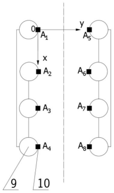
[0012] Step 1. Install a laser ranging sensor on each leg of the jacket of the offshore platform. The laser ranging sensor is installed vertically upwards, and the top surface of the laser ranging sensor is at the same level as the top surface of the jacket leg. For the convenience of description, a jacket with two rows of eight legs is taken as an example to illustrate, and a laser distance measuring sensor A is installed on the inner side of the legs of the jacket 1 -A 8 .

[0013] Step 2. Using the laser ranging sensor to measure and obtain the three-dimensional coordinates of multiple discrete points on the bottom surface of the upper module, the specific process is as follows:

[0014] The first step is to select the laser ranging sensor A 1 The center point of the laser emission port is the origin, and a space rectangular coordinate ...


PUM


Abstract

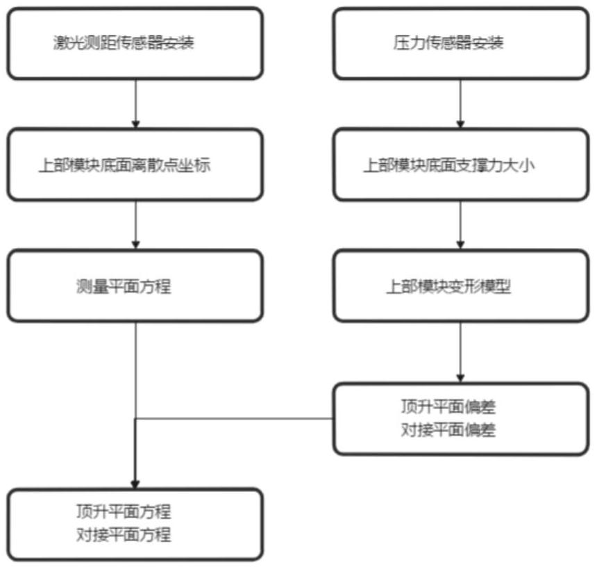
The invention discloses a pose monitoring method suitable for a floating support installation jacking plane and a butt joint plane. The pose monitoring method comprises the steps that eight laser distance measuring sensors are installed on a jacket pile leg, distance data are measured in the butt joint process, coordinates of discrete points at the bottom of an upper module are obtained according to the position relation, and a measurement plane equation is calculated; pressure sensors are installed in the four hydraulic cylinders, pressure values are measured, the jacking force of all positions is calculated, static analysis is conducted in ANSYS to obtain an upper module deformation model, and jacking plane deviation and butt joint plane deviation are calculated through secondary development; and a jacking plane equation and a butt joint plane equation are obtained in combination with the deviation value and the measurement plane equation. The butt joint precision of the upper modules in the floating support installation process can be improved, the anti-interference performance of a monitoring system is enhanced, and the safety of the butt joint process is guaranteed.

Description

technical field [0001] The invention relates to a method for monitoring the position and posture of a plane, in particular to a method for monitoring the position and posture of a jacking plane and a docking plane installed with a float. Background technique [0002] During the docking process of the floatover installation module, the upper module slowly descends to the supporting legs of the jacket under the joint action of the hydraulic system, the water level ballast system and the tide. Affected by factors such as wind, waves, currents, and tides, the upper module needs to be kept stable through the motion compensation system. The most important part of the motion compensation system is the monitoring of the real-time pose of the upper module. The traditional position and attitude monitoring method is to use lidar to monitor the upper module. This method has large hysteresis, low monitoring accuracy, limited monitoring range, high equipment cost, and poor environmental a...

Claims


Application Information

Patent Timeline
Patent Type & Authority Applications(China)
IPC IPC(8): G01B11/00G01B11/14G06F30/23G06F119/14
CPCG01B11/00G01B11/002G01B11/14G06F30/23G06F2119/14
Inventor 邵鹏松章青张子波蒋晗姚旭张子峰
Owner TIANJIN UNIV
Learn More