Antenna assembly

Active Publication Date: 2014-01-23
NILSSON JACK
View PDF4 Cites 0 Cited by
  • Summary
  • Abstract
  • Description
  • Claims
  • Application Information

AI Technical Summary

Benefits of technology

The invention is about an antenna assembly that includes a cable and a spirally wound sheet of conductive material that serves as a radiative element. The radiative element can send and receive electromagnetic signals. The height of the radiative element is equal to the width of the sheet of conductive material, and the assembly has a characteristic wavelength associated with its lowest operating frequency. The invention also includes a method for forming a wideband and multiband omnidirectional antenna by rolling a sheet of conductive material about an end and preventing it from contacting itself. The technical effects of this invention include improved efficiency, wider bandwidth, and greater stability of the antenna assembly.

Problems solved by technology

The disclosure of Nilsson and prior art coiled antennas all suffer from the same defects of a large size relative to their intended frequency use and narrow banded qualities.
As such, conventional coiled antennas are large and bulky and / or operate at a very narrow band.

Method used


Image

  • Antenna assembly
  • Antenna assembly
  • Antenna assembly

Examples


Embodiment Construction

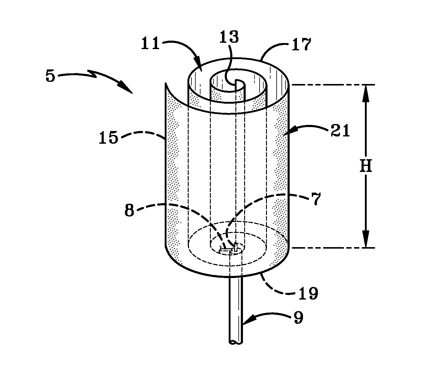
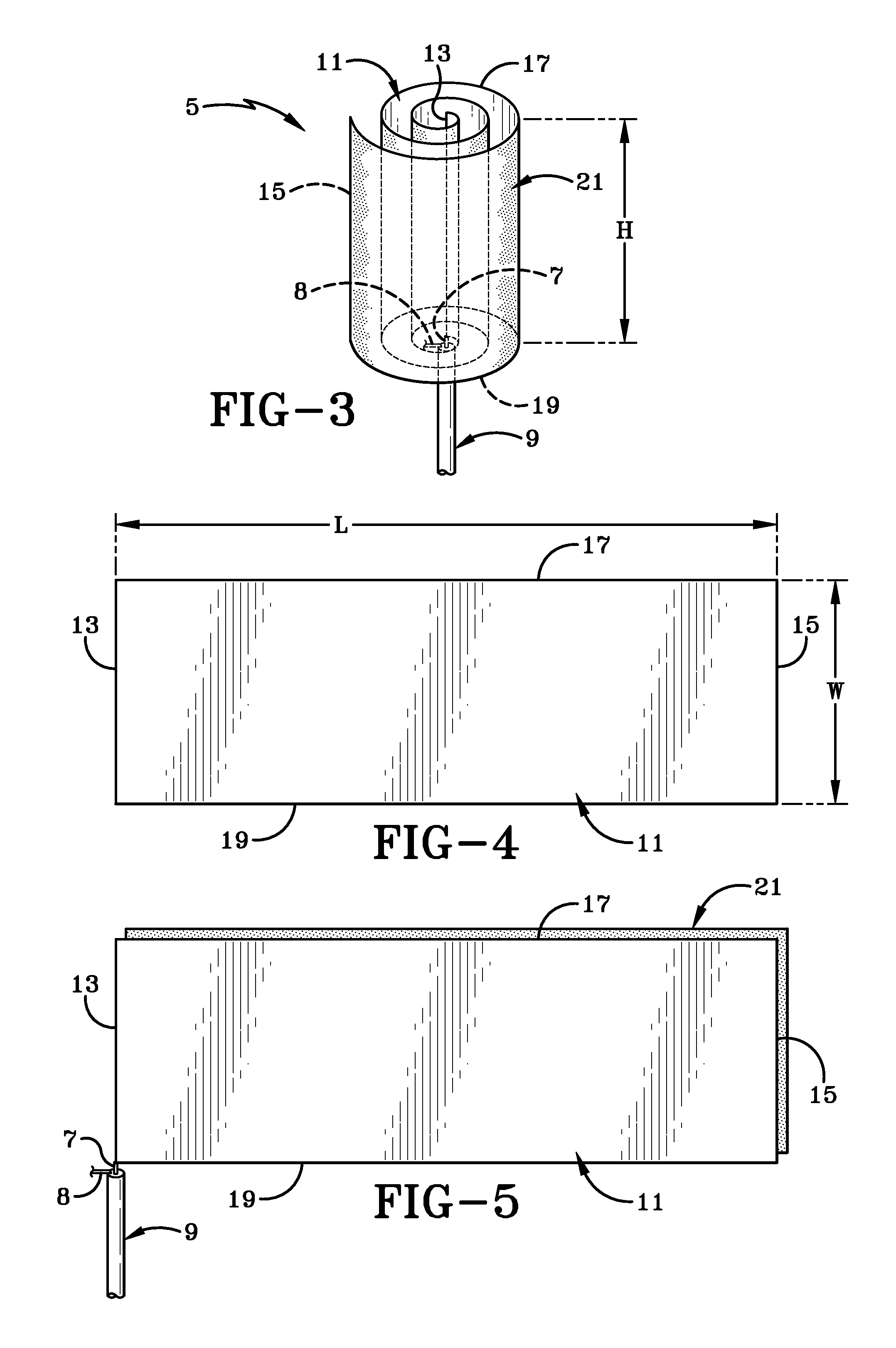
[0019]The compact wide-band / multi-band omnidirectional antenna assembly of the present invention is shown in FIGS. 2-8, and is indicated generally at 1. Antenna assembly 1 is used for transmitting and receiving radio frequency signals in accordance with various aspects of the present invention.

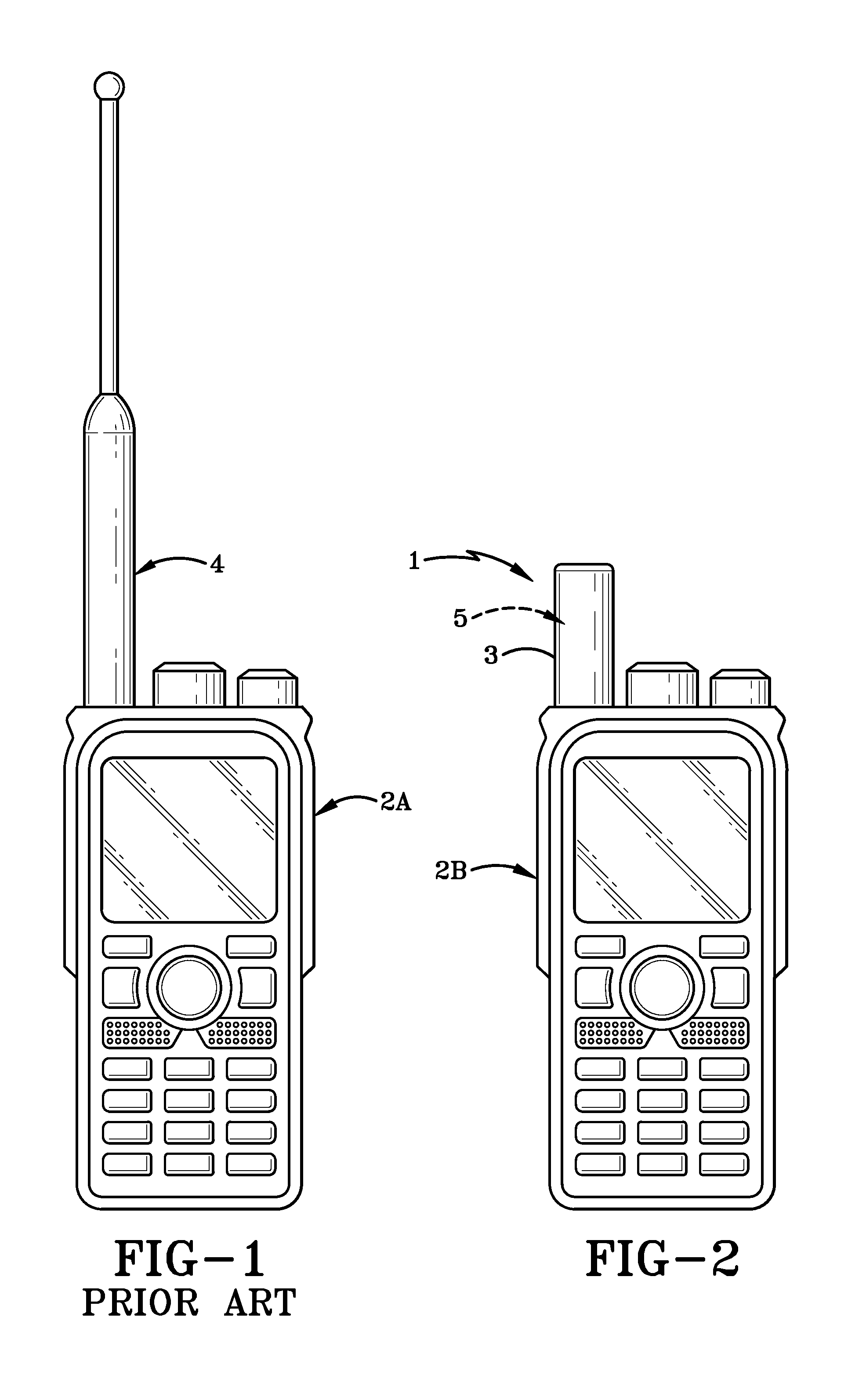
[0020]As shown in FIGS. 1 and 2, antenna assembly 1 is a smaller alternative to prior art antennas for comparable intended frequencies, as the prior art antennas include a much larger profile while radiating within a smaller frequency band. A comparison with the prior art is shown in FIGS. 1 and 2, wherein FIG. 1 includes a handheld radio 2A supplied with a prior art antenna assembly 4. Antenna assembly 4 is lengthy and radiates within a narrow band spectrum. As shown in FIG. 2, antenna assembly 1 is generally much smaller and compact yet radiates within a wider band, even when a radome 3 is included in antenna assembly 1. Thus, handheld radio 2B is more compact while providing better frequenc...


PUM

PropertyMeasurementUnit
Fractionaaaaaaaaaa
Fractionaaaaaaaaaa
Massaaaaaaaaaa

Abstract

The present invention relates to an antenna assembly for transmitting and receiving electromagnetic waves. More particularly, this invention relates to a wideband and multiband omnidirectional antenna assembly for sending and receiving radio waves. Specifically, this invention relates to a radiative antenna element formed by way of a single-fed spiraled sheet of conductive material. The conductive material is interlaced with a dielectric material to form the radiative element. The radiative element includes a height of substantially less than ¼ of the characteristic wavelength of the lowest operating frequency.

Description

CROSS-REFERENCE TO RELATED APPLICATION[0001]This application claims priority from U.S. Provisional Application Ser. No. 61 / 741,346, filed Jul. 18, 2012, the disclosure of which is incorporated herein by reference.BACKGROUND OF THE INVENTION[0002]1. Technical Field[0003]This invention relates to a device for transmitting and receiving electromagnetic waves. More particularly, this invention relates to a wideband and multiband omnidirectional antenna for sending and receiving radio waves. Specifically, this invention relates to a radiative antenna element formed by way of a single-fed spiraled sheet of conductive material interlaced with a dielectric material and having a height of markedly less than ¼ of the characteristic wavelength of the lowest operating frequency.[0004]2. Background Information[0005]Heretofore, different coil geometries have been used for antenna designs. Examples include helical coil variations, including those found in U.S. Patent Application Publication No. 20...

Claims


Application Information

Patent Timeline
IPC IPC(8): H01Q1/36
CPCH01Q1/36Y10T29/49016
Inventor NILSSON, JACK
Owner NILSSON JACK
Why Eureka
Try Eureka