Color filter substrate, touch display panel and touch display device

a technology of touch display panel and substrate, which is applied in the direction of electronic switching, pulse technique, instruments, etc., can solve the problems of difficult reduction of thickness and may not meet user requirements of touch display panel and devi

Inactive Publication Date: 2014-01-23
TIANJIN FUNA YUANCHUANG TECH
View PDF5 Cites 14 Cited by
  • Summary
  • Abstract
  • Description
  • Claims
  • Application Information

AI Technical Summary

Benefits of technology

The patent text is discussing the issue of thick touch display panels and devices caused by the use of optical clear adhesive. The technical effect is that the optical clear adhesive makes it difficult to reduce the thickness of the touch display panels and devices, which may not meet users' requirements.

Problems solved by technology

However, because of the optical clear adhesive, a thickness of the touch display panels and devices is hard to reduce.
Thus, the touch display panels and devices may be not meet users' requirements.

Method used


Image

  • Color filter substrate, touch display panel and touch display device
  • Color filter substrate, touch display panel and touch display device
  • Color filter substrate, touch display panel and touch display device

Examples


Embodiment Construction

[0016]Reference will now be made to the drawings to describe various embodiments in detail.

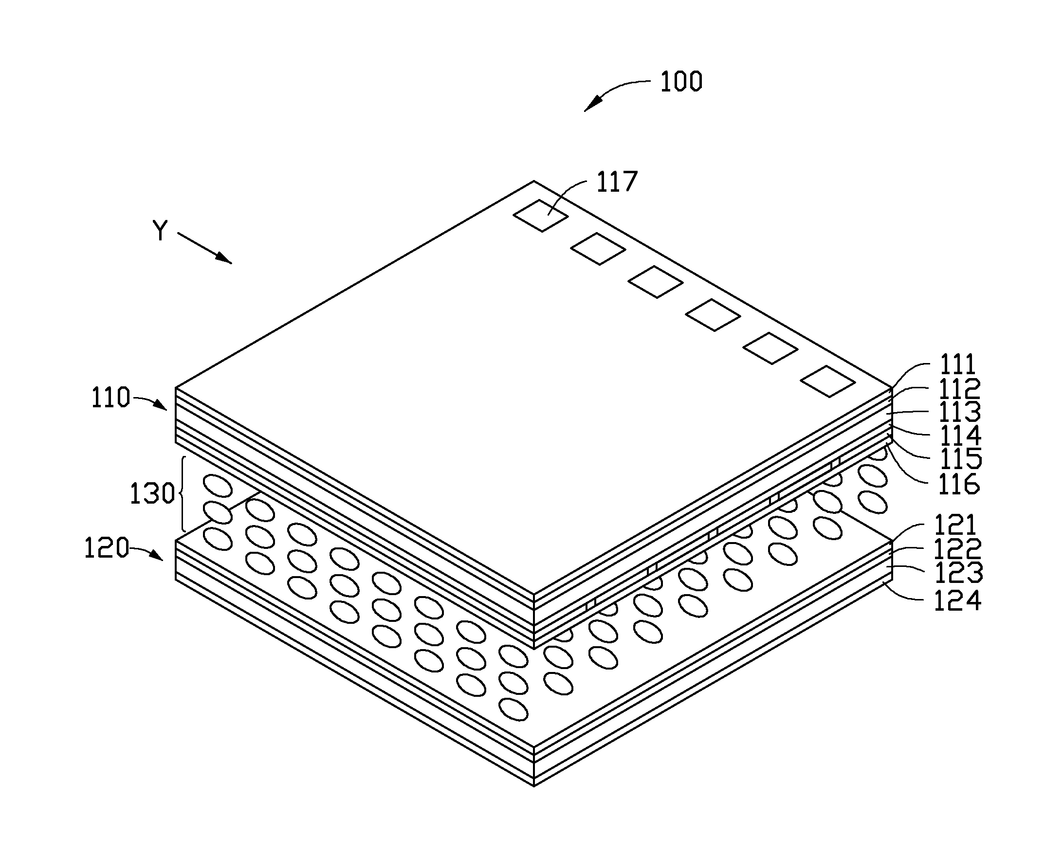
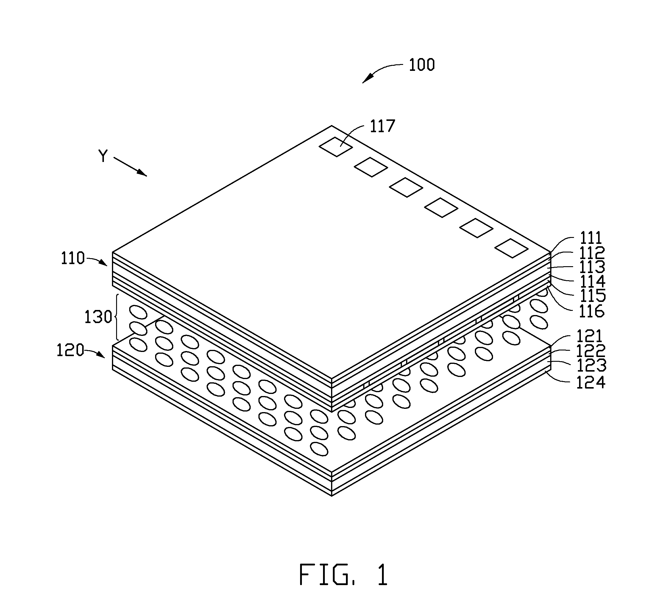
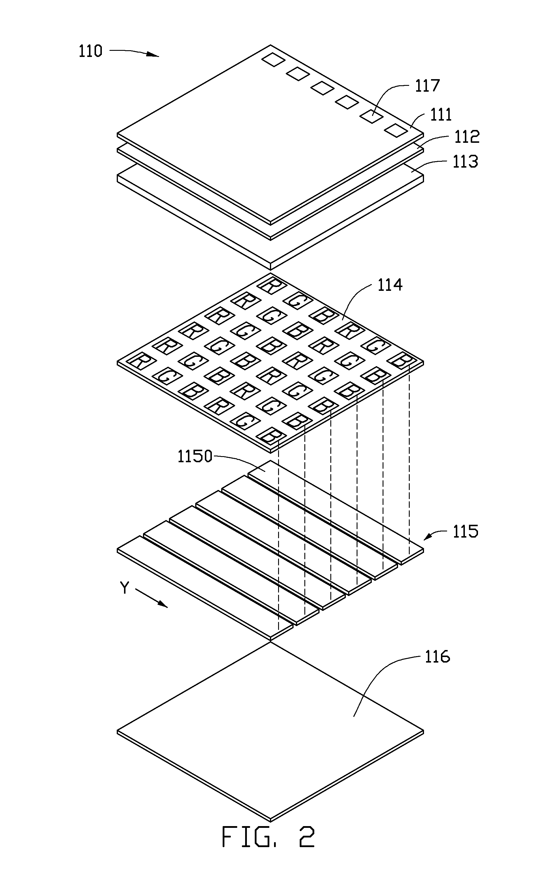
[0017]Referring to FIG. 1, a touch display panel 100 according to an embodiment of the present disclosure includes a first substrate 110, a second substrate 120 facing the first substrate 110, and a liquid crystal layer 130 sandwiched between the first substrate 110 and the second substrate 120. The first substrate 110 can be a color filter substrate and includes a transparent conductive layer 111, an upper polarizer 112, a first base 113, a color filter layer 114, a common electrode layer 115, an upper orientation layer 116, and a plurality of sensitive electrodes 117. The second substrate 120 includes a lower orientation layer 121, a driving layer 122, a second base 123, and a lower polarizer 124.

[0018]The first base 113 can be a glass substrate, a side of the first base 113 adjacent to the liquid crystal layer 130 is defined as a first side of the first base 113, and a side of the first bas...


PUM

PropertyMeasurementUnit
transparent conductiveaaaaaaaaaa
electric anisotropyaaaaaaaaaa
resistivityaaaaaaaaaa

Abstract

A color filter substrate for a touch display panel includes a common electrode layer and a transparent conductive layer. The common electrode layer includes a plurality of common electrodes each extending along a first direction. The transparent conductive layer exhibits electric anisotropy and has the lowest resistivity along a second direction. The transparent conductive layer and the common electrode layer cooperatively define a capacitive touch sensitive structure.

Description

CROSS-REFERENCE TO RELATED APPLICATIONS[0001]This application claims all benefits accruing under 35 U.S.C. §119 from China Patent Application No. 201210254436.4, filed on Jul. 23, 2012 in the China Intellectual Property Office, the content of which is hereby incorporated by reference. This application is related to commonly-assigned applications entitled, “POLARIZER”, U.S. application Ser. No. 13 / 730,711, filed Dec. 28, 2012; “POLARIZER”, U.S. application Ser. No. 13 / 730,884, filed Dec. 29, 2012, “LIQUID CRYSTAL DISPLAY MODULE”, U.S. application Ser. No. 13 / 837,266, filed Mar. 15, 2013, and “LIQUID CRYSTAL DISPLAY MODULE”, U.S. application Ser. No. 13 / 837,359 filed Mar. 15, 2013; “LIQUID CRYSTAL DISPLAY MODULE”, U.S. application Ser. No. 13 / 869,958, filed Apr. 25, 2013, and “LIQUID CRYSTAL DISPLAY MODULE”, U.S. application Ser. No. 13 / 869,959 filed Apr. 25, 2013; “METHOD FOR MAKING LIQUID CRYSTAL DISPLAY MODULE”, U.S. application Ser. No. 13 / 869,961, filed Apr. 25, 2013; “METHOD FOR...

Claims


Application Information

Patent Timeline
Patent Type & Authority Applications(United States)
IPC IPC(8): H03K17/96G02F1/1333
CPCH03K17/9622G02F1/13338B82Y15/00B82Y30/00G02F1/13439G06F2203/04103G09G3/3648G06F3/0445G06F3/0446G02F1/134318
Inventor WU, HO-CHIEN
Owner TIANJIN FUNA YUANCHUANG TECH
Why Eureka
Try Eureka