Cold effect applicator tip

a technology of applicator tips and cosmetic products, which is applied in the direction of combustion types, packaging foodstuffs, packaged goods, etc., can solve the problems of reducing affecting the oxidation effect of cosmetic products, so as to reduce the oxidation risk of cosmetic products, reduce the risk of oxidation, and manufacture cheap

Inactive Publication Date: 2014-01-23
ALBEA SERVICES SAS
View PDF11 Cites 8 Cited by
  • Summary
  • Abstract
  • Description
  • Claims
  • Application Information

AI Technical Summary

Benefits of technology

[0021]In particular, an object of the present application is to provide a cold effect applicator tip, the use of which is electrically economical and its manufacture cheap, while limiting the oxidation risk of the cosmetic product to be applied.
[0023]Thus, in consequence of the applicator tip, it is possible to confer a cold effect while avoiding the use of a massive metal applicator being able to oxide the cosmetic product and reducing the manufacturing cost of the applicator tip with respect to the ceramic applicator tips. It is also possible thanks to the use of a filled plastic material to obtain applicator tips with various forms related to the assembling functions.

Problems solved by technology

Consequently, the use of such applicator tip is power consuming.
However, the use of a metal is not recommended, in particular because the metal must come in contact with the cosmetic product being applied.
Indeed, the metal can lead to an oxidation of the cosmetic product, thereby damaging its properties.
The ceramic working is relatively complex.

Method used


Image

  • Cold effect applicator tip
  • Cold effect applicator tip
  • Cold effect applicator tip

Examples


example 1

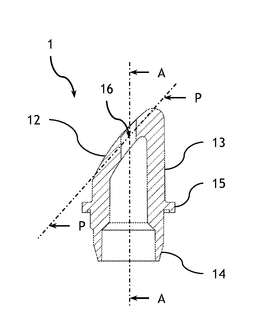
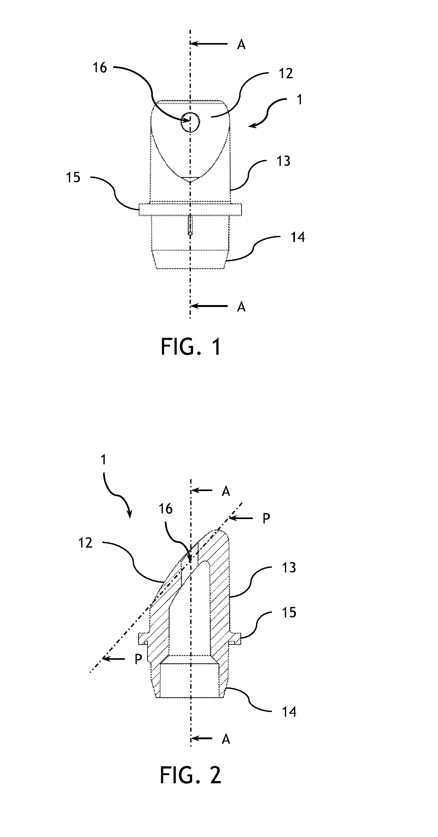
[0071]The applicator tip of example 1 comprises a convex external application surface having in its largest part a radius of curvature of 25 mm. Such application surface extends according to an inclined plane with respect to the axis of the applicator tip. The thickness of the material under the application surface is about 2.2 mm. The applicator tip comprises a ring wall of a thickness of 2.2 mm and is configured according to a cylindrical tube with a circular cross section which is beveled with an acute angle of 42° on one of the ends thereof according to the inclined plane. The external radius of the circular cross section is 9.8 mm.

[0072]On the other non beveled end of the tube, the edges of the ring wall are tapered so as to present a thickness of 1 mm.

[0073]A circular circumferential stop is provided around the ring wall and extends from the latter. The external radius of the circular circumferential stop is 12.5 mm.

[0074]The applicator tip presents a through orifice with a ra...

example 2

[0075]The applicator tip of example 2 comprises a convex external application surface having in its largest part a radius of curvature of 45 mm. Such application surface extends according to an inclined plane with respect to the axis of the applicator tip. The thickness of the material under the application surface is about 4.7 mm. The applicator tip comprises a ring wall with a thickness of 4.7 mm and is configured according to a cylindrical tube with a circular cross section which is beveled with an acute angle of about 42° on one of its ends according to the inclined plane. The external radius of the circular cross section is 9.8 mm.

[0076]On the other non beveled end of the tube, the edges of the ring wall are tapered so as to present a thickness of 2 mm.

[0077]A circular circumferential stop is provided around the ring wall and extends from the latter. The external radius of the circular circumferential stop is 11 mm.

[0078]Between the other end and the circumferential stop, the a...

example 3

[0080]Examples of metallic or organic filled plastic materials are given in the table 1 herein below.

TABLE 1Plastic 1Plastic 2Plastic 3Plastic 4BasePEEKPPSPPAPA6Type of fillersOrganic:Organic:Organic:Metallic:carbon andcarbon andcarbon andmetalgraphitegraphitegraphitemineralfiberfiberfibersaltsQuantity of fillers40 wt %40 wt %40 wt %45 wt %Effusivity7370713057204010J · K−1 · m−2 ·sec−1 / 2Thermal22222010conductivityW / (m · K)Diffusivity m2 / sec8.99.512.26.2Volume weight1.641.651.561.6g / cm3


PUM


Abstract

The present application relates to a cold effect applicator tip for cosmetic products, characterized in that the applicator tip is made of a plastic material comprising organic fillers, metallic fillers or a mixture of both. The present application also relates to a container for cosmetic products with a cold effect applicator tip is also provided, comprising a reservoir to contain a cosmetic product and an applicator tip such as above described.

Description

CROSS REFERENCE TO RELATED APPLICATIONS[0001]This application claims priority under 35 U.S.C. §119(a) to French Patent Application Serial Number 1257054, filed Jul. 20, 2012, entitled “COLD EFFECT APPLICATOR TIP”, the entirety of which is incorporated herein by reference.BACKGROUND OF THE INVENTION[0002]1. Field of the Invention[0003]The invention relates to the field of applicator tips for cosmetic products and more particularly the field of cold effect applicator tips for cosmetic products.[0004]2. Description of Related Art[0005]There are applicator tips allowing a cold effect to be conferred to the user when the latter put the applicator tip in contact with his skin.[0006]For example, the document US 2003 / 0100936 describes an applicator tip allowing a cold effect to be conferred to the user. Such applicator tip comprises a hollow roller adapted to be put in contact with the user's skin. Such hollow roller may be made of a metal, a ceramics, a plastics, a quartz sapphire. Said ho...

Claims


Application Information

Patent Timeline
Patent Type & Authority Applications(United States)
IPC IPC(8): A45D40/26
CPCA45D40/26A45D34/04A45D2200/15
Inventor BONNIN, THOMASEDMOND, AURELIE
Owner ALBEA SERVICES SAS
Why Eureka
Try Eureka