Electrochromic device, optical filter, lens unit, imaging apparatus, window member, and driving method

a technology of optical filter and optical filter, which is applied in the direction of camera filters, instruments, constructions, etc., can solve the problems of affecting the balance of electron transfer, reducing the transparency of the ec device in a decolored state, and inhibiting the achievement of an absorption spectrum in a colored sta

Active Publication Date: 2019-06-06
CANON KK
View PDF0 Cites 5 Cited by
  • Summary
  • Abstract
  • Description
  • Claims
  • Application Information

AI Technical Summary

Benefits of technology

[0011]An electrochromic device according to the present disclosure includes an electrochromic element including a first electrode, a second electrode, and an electrochromic layer disposed between the first electrode and the second electrode; and a controller for the electrochromic element, wherein the electrochromic layer contains an anodic electrochromic compound and an oxidizable substance, the oxidizable substance is a substance which substantially does not undergo a color change due to oxidation and whose oxidant is not reduced, an oxidation reaction of the oxidizable substance is less likely to occur than an oxidation reaction of the anodic electrochromic compound, and the controller is configured to control oxidation of the oxidizable substance based on a charge balance of the electrochromic element.

Problems solved by technology

Specifically, even when the state of an EC device is changed from a colored state to a decolored state, a part of the organic EC compound is left in a colored state without being decolored, which decreases the transparency of the EC device in a decolored state.
This may be caused by “charge imbalance” in which the balance of electron transfer is disturbed by, for example, deterioration of an organic EC compound contained in an EC layer.
If a charge imbalance is caused in a complementary EC device, the ratio of a colored body of an anodic EC compound and a colored body of a cathodic EC compound in a colored state changes, which may inhibit achievement of an absorption spectrum in a colored state desired during design stages.
In the method that uses a redox buffer in PTL 1, the residual coloring can be suppressed, but a charge imbalance between electrodes cannot be eliminated.
Therefore, the ratio of a colored body of an anodic EC compound and a colored body of a cathodic EC compound in a colored state cannot be corrected.

Method used


Image

  • Electrochromic device, optical filter, lens unit, imaging apparatus, window member, and driving method
  • Electrochromic device, optical filter, lens unit, imaging apparatus, window member, and driving method
  • Electrochromic device, optical filter, lens unit, imaging apparatus, window member, and driving method

Examples


first embodiment

[0044]Configuration of EC Device

[0045]The configuration of an electrochromic (hereafter, “electrochromic” may be referred to as “EC”) device 500 according to this embodiment will be described. FIG. 5 schematically illustrates the configuration of an EC device 500. The EC device 500 according to this embodiment includes an EC element 100 and a driving unit 510.

[0046]The configuration of an EC device is not limited to the configuration according to this embodiment. It is sufficient that the EC device includes an EC element including at least a first electrode, a second electrode, and an EC layer disposed between the first electrode and the second electrode.

[0047]Structure of EC Element

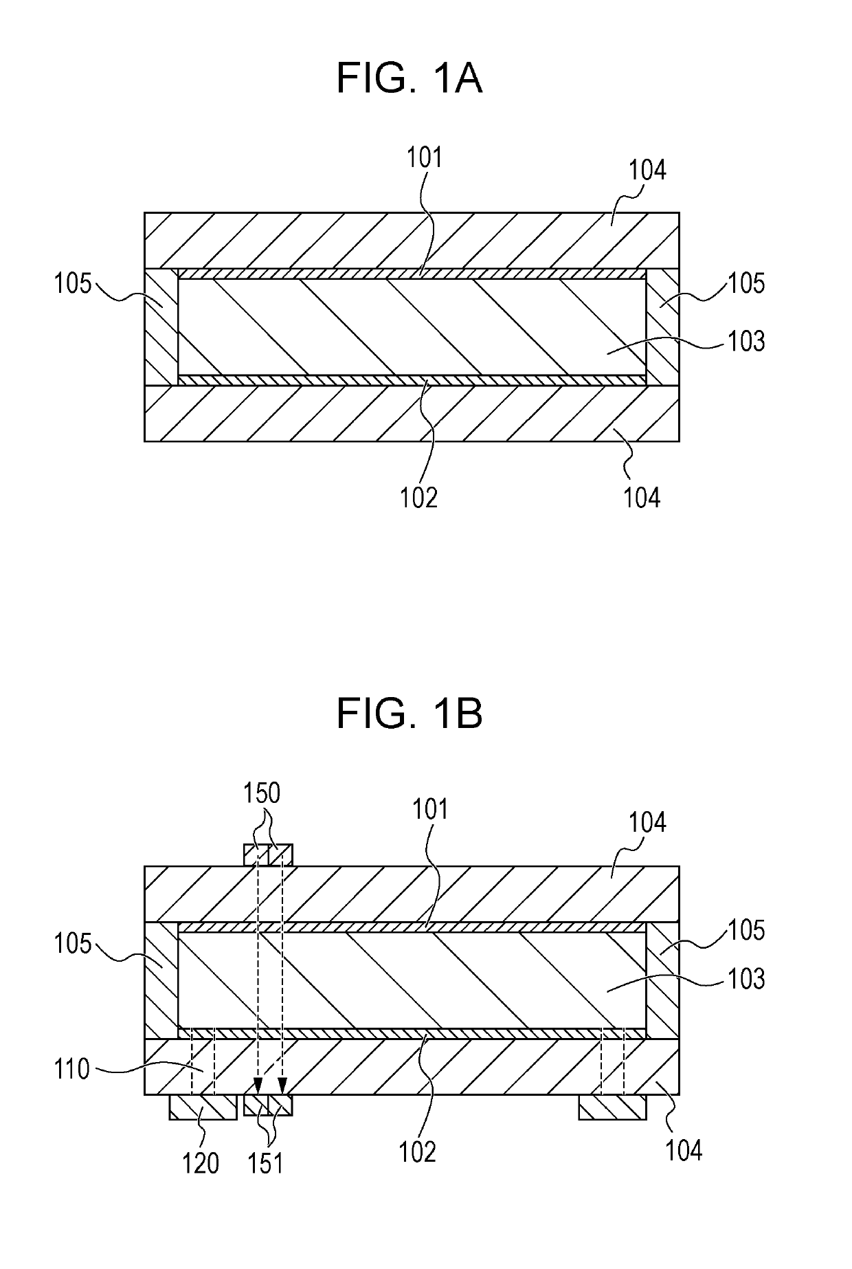
[0048]The structure of the EC element 100 will be described with reference to FIGS. 1A and 1B. FIGS. 1A and 1B schematically illustrate the structure of the EC element 100.

[0049]The EC element 100 includes a pair of substrates 104, a first electrode 101 and a second electrode 102 disposed between the pai...

second embodiment

[0196]An EC element 700 according to this embodiment will be described with reference to FIGS. 7A and 7B. The EC element 700 is an EC element including third electrodes 730. FIG. 7A is a top view illustrating the structure of the EC element 700 and FIG. 7B is a sectional view illustrating the structure of the EC element 700.

[0197]The EC element 700 includes a first electrode 701, a second electrode 702, an EC layer 703, substrates 704, a sealing member 705, and third electrodes 730. The first electrode 701 and the second electrode 702 are disposed between the pair of substrates 704 so as to face each other. The EC layer 703 is disposed between the first electrode 701 and the second electrode 702. The sealing member 705 is disposed between the pair of substrates 704, and the pair of substrates 704 and the sealing member 705 constitute a cell. An opening 710 is formed in the cell and sealed with a sealant 720. The first electrode 701, the second electrode 702, the EC layer 703, the su...

third embodiment

[0206]The EC element according to this embodiment is the same as that in the first embodiment, except that an oxidation-reduction substance that satisfies the following conditions (a) to (c) or (d) to (f) is further contained in the EC layer 103 according to the first embodiment.

[0207]As described above, the oxidizable substance is a substance that satisfies the conditions (A) to (D) and irreversibly causes an electrochemical oxidation reaction. The reducible substance is a substance that satisfies the conditions (E) to (H) and irreversibly causes an electrochemical reduction reaction. In addition, the EC layer 103 according to this embodiment contains a plurality of oxidation-reduction substances that electrochemically cause reversible oxidation-reduction reactions. The plurality of oxidation-reduction substances are constituted by at least one EC compound and an oxidation-reduction substance that satisfies the following conditions (a) to (c) or (d) to (f). The EC layer 103 may fur...


PUM

PropertyMeasurementUnit
charge imbalanceaaaaaaaaaa
electrochromicaaaaaaaaaa
anodic electrochromicaaaaaaaaaa

Abstract

An electrochromic device according to the present disclosure includes an electrochromic element that includes a first electrode, a second electrode, and an electrochromic layer disposed between the first electrode and the second electrode. The electrochromic layer contains an anodic electrochromic compound and an oxidizable substance. The oxidizable substance is a substance which substantially does not undergo a color change due to oxidation and whose oxidant is not reduced. An oxidation reaction of the oxidizable substance is less likely to occur than an oxidation reaction of the anodic electrochromic compound. A controller is configured to control oxidation of the oxidizable substance based on a charge balance of the electrochromic element.

Description

CROSS-REFERENCE TO RELATED APPLICATIONS[0001]This application is a Continuation of International Patent Application No. PCT / JP2017 / 026393, filed Jul. 21, 2017, which claims the benefit of Japanese Patent Application No. 2016-144986, filed Jul. 23, 2016, both of which are hereby incorporated by reference herein in their entirety.TECHNICAL FIELD[0002]The present disclosure relates to an electrochromic device and an optical filter, a lens unit, an imaging apparatus, and a window member that use the electrochromic device, and a driving method for the electrochromic device.BACKGROUND ART[0003]Compounds having electrochromic characteristics (hereafter, “electrochromic” may be referred to as “EC”) with which optical properties (absorption wavelength, absorbance) of a substance change through an electrochemical oxidation-reduction reaction are referred to as EC compounds. Electrochromic devices (EC devices) that use such an EC compound are applied to, for example, display apparatuses, varia...

Claims


Application Information

Patent Timeline
Patent Type & Authority Applications(United States)
IPC IPC(8): G02F1/1503G02F1/163G03B11/00E06B9/24E06B3/67G02F1/1514
CPCG02F1/1503G02F1/163G03B11/00E06B9/24E06B3/6722E06B2009/2464G02F1/1514G02F1/15165G02F1/155
Inventor KUBO, WATARUYAMADA, KENJIIGAWA, SATOSHI
Owner CANON KK
Why Eureka
Try Eureka