

Method for welding aluminum alloy materials and aluminum alloy panel produced thereby
- Summary
- Abstract
- Description
- Claims
- Application Information
AI Technical Summary
Benefits of technology
Problems solved by technology
Method used
Image

Examples
Embodiment Construction
[0036]To avoid, minimize or prevent the occurrence of color or lightness variations between a portion of the surface that corresponds to (covers) a welded area and other surface portions that correspond to (cover) non-welded area(s) in the anodized coating formed on the surface(s) of aluminum alloy materials, it is preferred to restrict both the distribution density of second phase particles in the aluminum alloy materials and the conditions under which friction stir welding is performed, as will be further discussed in the context of a preferred embodiment below.
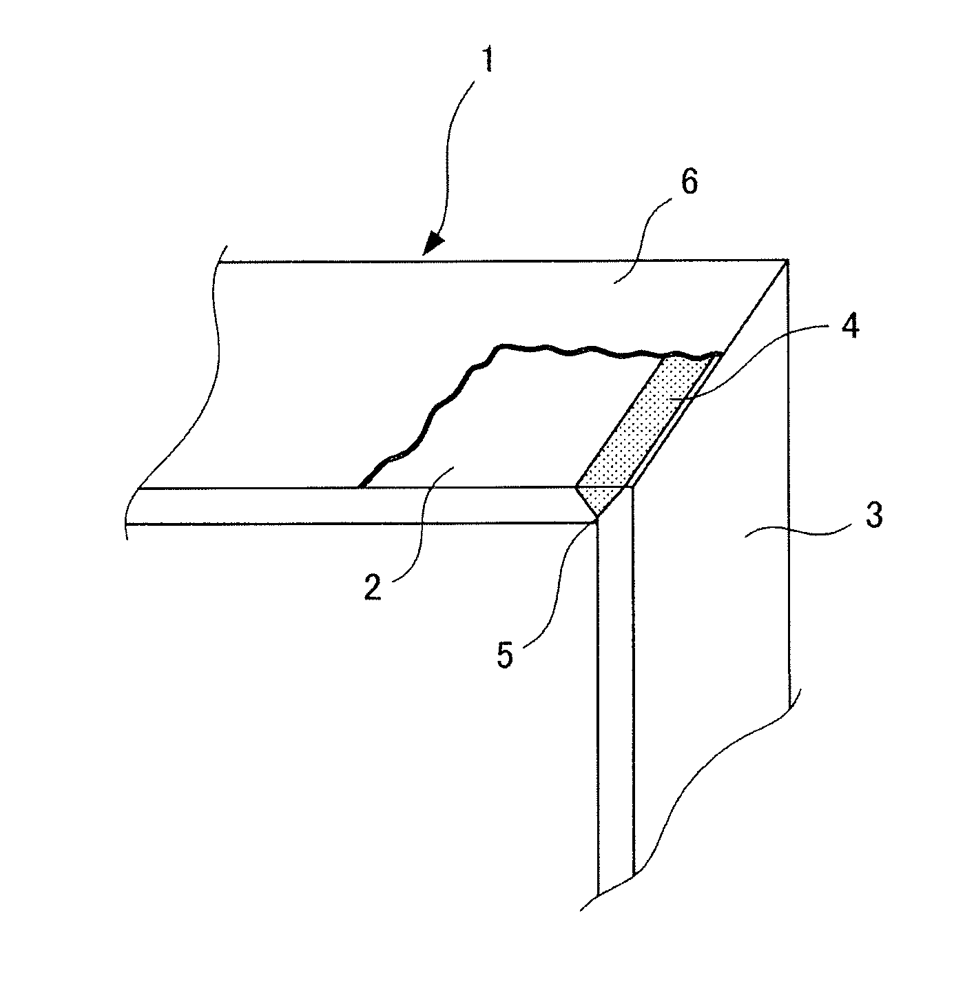
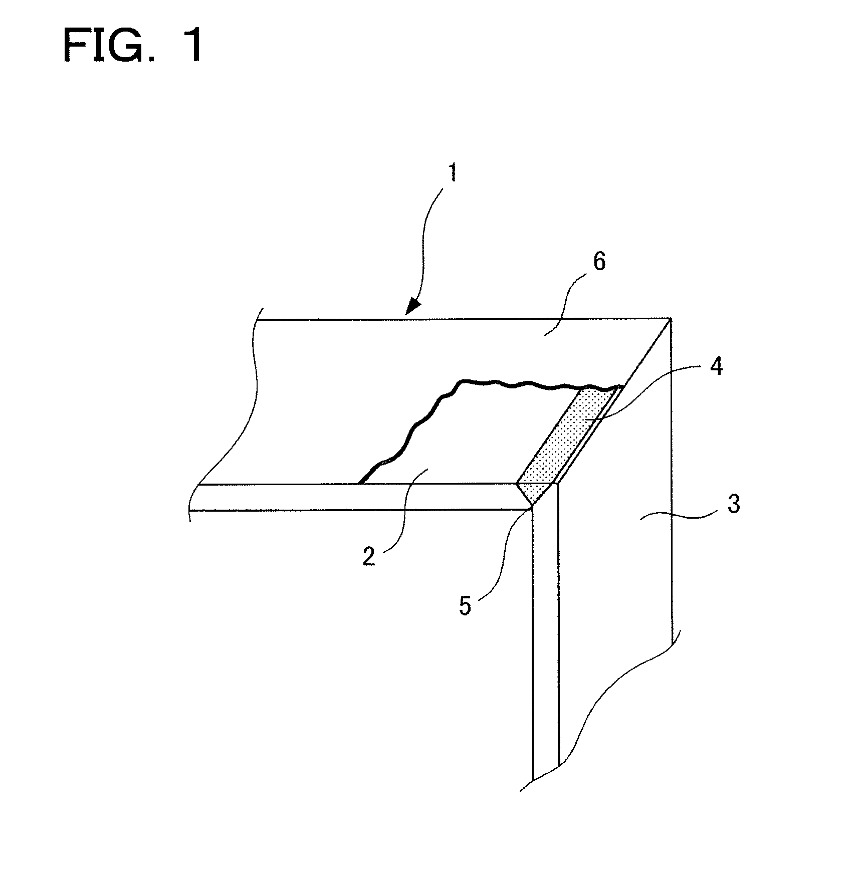
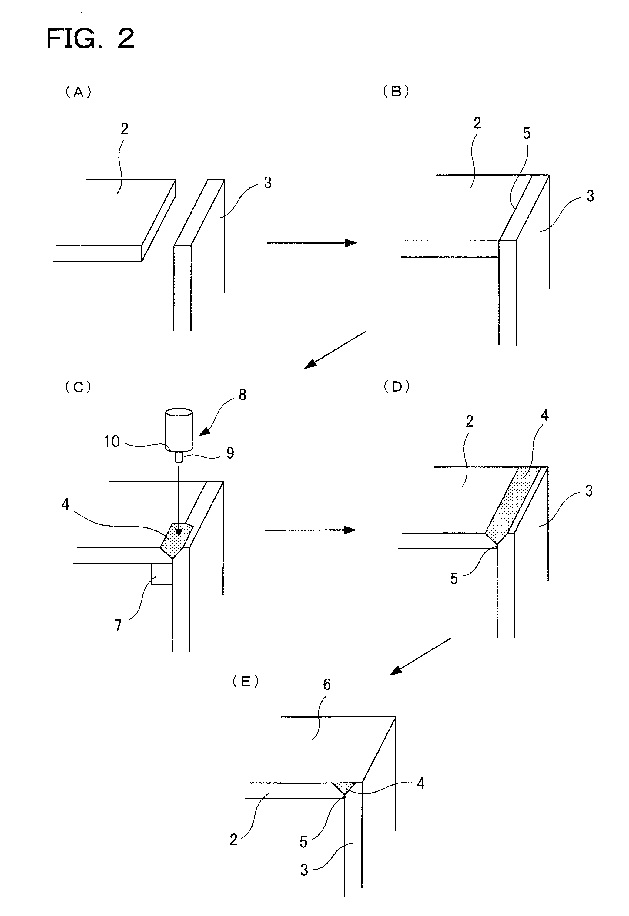
[0037]Referring to FIG. 1, an aluminum alloy panel 1 produced according the present method includes an aluminum alloy cover member 2 having a thickness of 2 mm, an aluminum alloy side member 3 having a thickness of 2 mm, and a welded area (weld) 4 disposed along a joint portion (e.g., a butt joint) 5 where the aluminum alloy cover member 2 and the aluminum alloy side member 3 are welded. After face milling the welded area 4...
PUM
| Property | Measurement | Unit |
|---|---|---|
| Length | aaaaa | aaaaa |
| Length | aaaaa | aaaaa |
| Time | aaaaa | aaaaa |
Abstract
Description
Claims
Application Information