
Cup-shaped plating apparatus

Inactive Publication Date: 2007-02-20
ELECTROPLATING ENGINEERS OF JAPAN LTD
View PDF10 Cites 1 Cited by
  • Summary
  • Abstract
  • Description
  • Claims
  • Application Information

AI Technical Summary

Benefits of technology

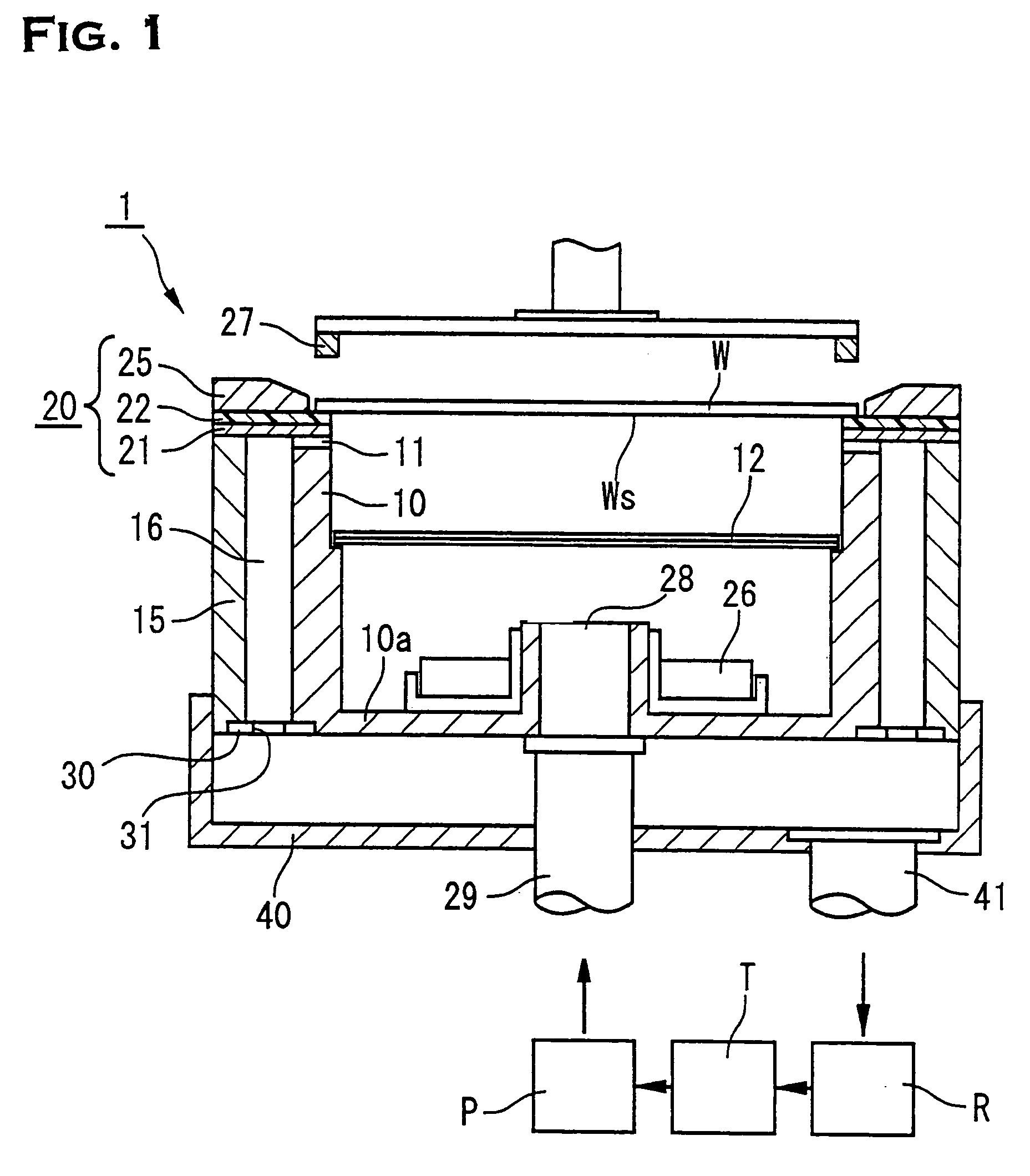
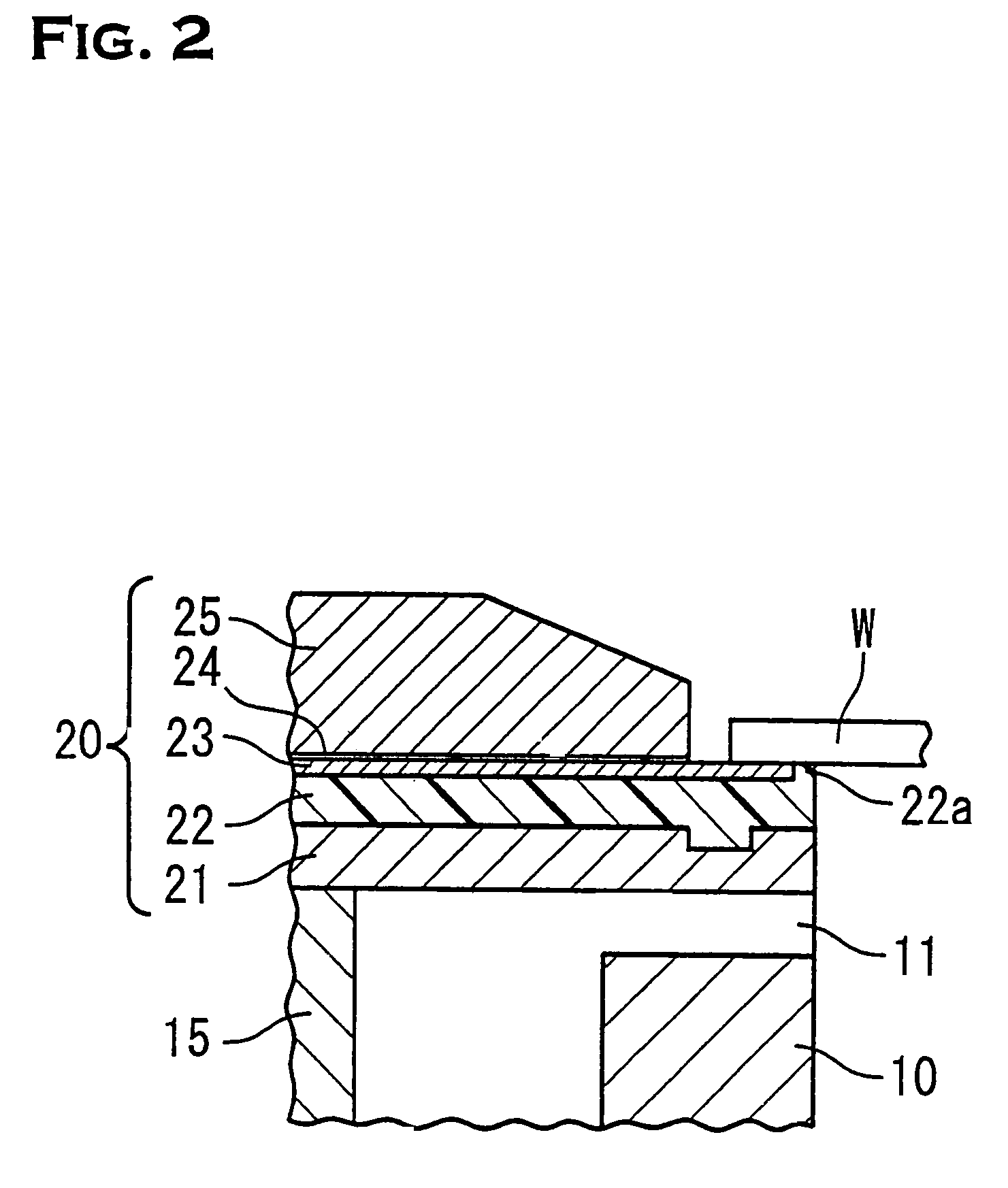
[0013]It is preferred that the cavity portion be formed so as to surround the plating tank. This is because if so, the outlet port can be formed on the outer peripheral surface of the plating tank along the whole circumference and because the plating solution can be discharged to outside the plating tank via the outlet port from any position in the outer peripheral region within the plating tank. When such a structure is used, the flow of the plating solution in the outer peripheral region within the plating tank becomes smoother and uniform, it is possible to more positively prevent the occurrence of nonuniformity and variations in the plating film thickness in the outer peripheral portion of the plating target surface.
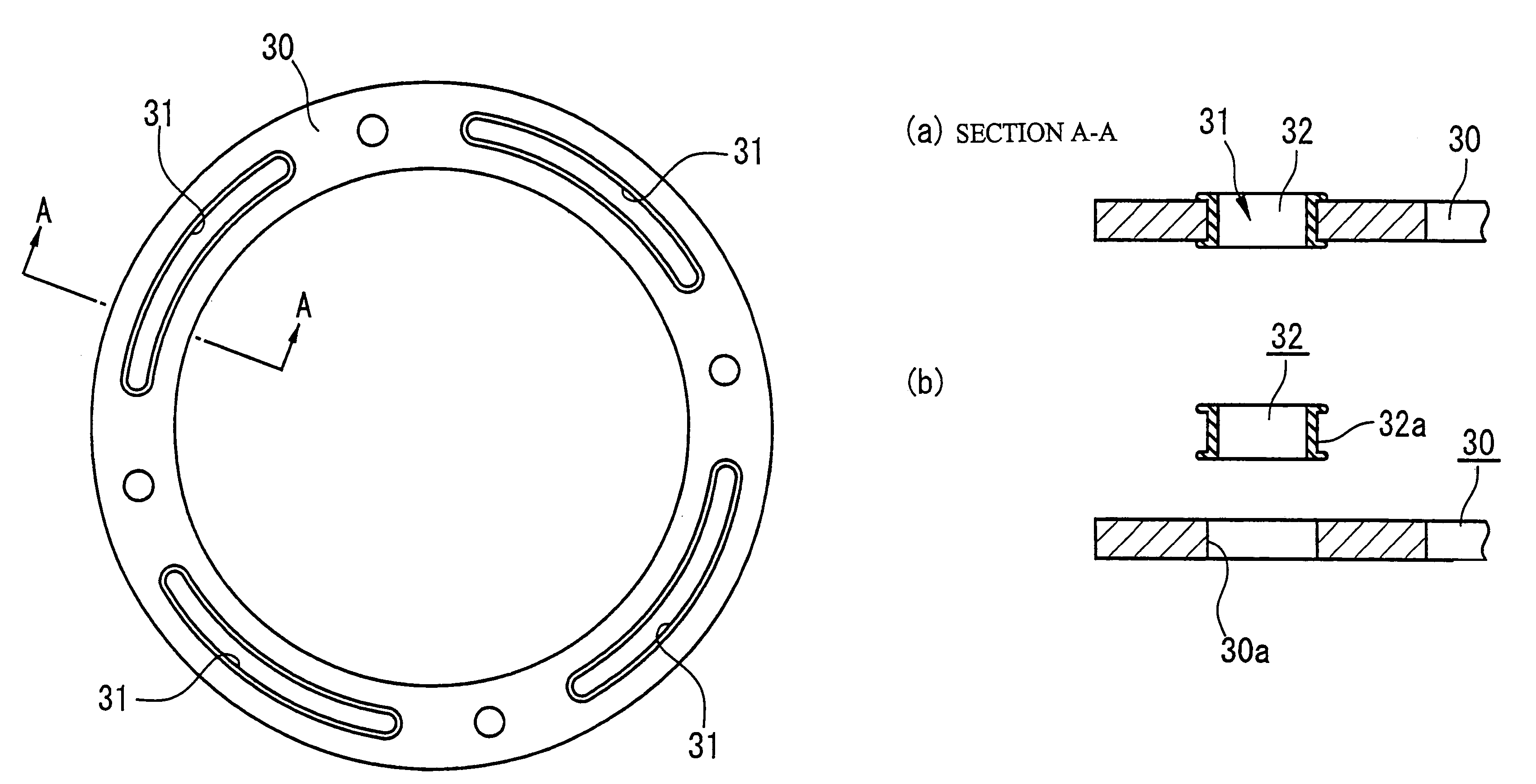
[0014]And it is preferred that a plurality of discharge ports be formed on the downstream side of the flow direction of the plating solution in the cavity portion so as to surround the plating tank. For example, in a case where the cavity portion is formed so as to surround a cylindrical plating tank, the downstream side of the flow direction of the plating solution refers to a position near the bottom of the plating tank, such as a bottom end portion of the cavity portion. In a case where the discharge port is formed in such a position, even when the total opening area is the same, the occurrence of nonuniformity and variations in the plating film thickness is more positively prevented by providing a plurality of discharge ports and forming the discharge ports in a distributed state. And when a plurality of discharge ports are provided, it is preferred that discharge ports of the same size be provided at equal intervals, because the occurrence of nonuniformity and variations in the plating film thickness is still further positively prevented.

Problems solved by technology

However, when plating treatment is performed during the continuous supply of a plating solution, nonuniform plating attributable to the flow of the plating solution may sometimes occur.

Method used


Image

  • Cup-shaped plating apparatus
  • Cup-shaped plating apparatus
  • Cup-shaped plating apparatus

Examples


example 1

[0036]In this embodiment, a plate 30 as shown in FIG. 3 was attached to the bottom end of the cavity portion 16. That is, the discharge port 31 had the shape of a slotted hole. Incidentally, the wafer to be plated had a diameter of 200 mm and the diameter of the plating target surface was 190 mm. The plating solution was a copper sulfate solution (solution temperature: 20° C.) and this plating solution was continuously fed through the supply tube into the plating tank at a rate of 15 liters / minute. The theoretical current density on the plating target surface during energization was 1 A / dm2.


PUM

PropertyMeasurementUnit
Thicknessaaaaaaaaaa
Compositionaaaaaaaaaa
Flow rateaaaaaaaaaa

Abstract

Provided is a cup-shaped plating apparatus which can plate the whole area of a plating target surface with a uniform film thickness. In a cup-shaped plating apparatus including a placement portion of an object to be plated which is provided at an opening end of a plating tank, means for supplying a plating solution into the plating tank, a plating solution outlet port which is formed in the plating tank, a cavity portion into which the plating solution which has flown out of the outlet port flows, a plating solution discharge port within the cavity portion, and a collection tank for the plating solution discharged from the discharge port, which subjects the object to be plated to plating treatment while supplying the plating solution into the plating tank, the shape and / or opening area of the discharge port formed on the downstream side of the cavity portion can be changed. If the shape and / or opening area of the discharge port formed on the downstream side of the cavity portion can be adjusted, it is possible to suppress nonuniform plating and variations in plating on a plating target surface by adjusting the shape and / or opening area.

Description

TECHNICAL FIELD[0001]The present invention relates to an apparatus for subjecting metals, semiconductor wafers, etc. to plating treatment and, more particularly, to the so-called a cup-shaped plating apparatus.BACKGROUND ART[0002]As one type of plating apparatus there is available a cup-shaped plating apparatus 100 used for the plating of wafers etc. As shown in FIG. 6, the cup-shaped plating apparatus 100 is provided with a plating tank 101 and a wafer placement portion 106 in a top opening of the plating tank 101. Within the plating tank is provided an anode (a positive electrode) 105, which is one electrode for electrolytic plating. Also, a cathode (a negative electrode) which is the other electrode for the same, a silver packing 107, etc. are attached to the placement portion 106. That is, when a wafer W is placed on the placement portion, a plating target surface Ws of the wafer W is brought into contact with a plating solution within the plating tank and a current is caused to...

Claims


Application Information

Patent Timeline
IPC IPC(8): C25D17/02C25D7/12C23C18/16H01L21/288
CPCC25D5/08H01L21/2885C25D17/001
Inventor ISHIDA, HIROFUMI
Owner ELECTROPLATING ENGINEERS OF JAPAN LTD
Learn More