Droplet generation system with features for sample positioning

Inactive Publication Date: 2014-01-23
BIO RAD LAB INC
View PDF8 Cites 57 Cited by
  • Summary
  • Abstract
  • Description
  • Claims
  • Application Information

AI Technical Summary

Benefits of technology

[0008]The present disclosure provides a system, including methods and apparatus, for forming droplets of an emulsion. The system may include a channel junction at which a stream of sample fluid is divided into droplets by a dividing flow of carrier fluid. The system also may include one or more features configured to position sample fluid for reduced contact between the sample fluid and on

Problems solved by technology

If droplet size cannot be controlled tightly, the resulting droplet polydispersity can increase an assay's sensitivity to false positives.
However, the performance o

Method used


Image

  • Droplet generation system with features for sample positioning
  • Droplet generation system with features for sample positioning
  • Droplet generation system with features for sample positioning

Examples


example 1

Droplet Generation with Undesired Variability

[0104]This example describes undesired variability in generated droplet size that can occur in a droplet generation system as a function of time, phase composition, and / or sample viscoelasticity, among others; see FIGS. 2-8.

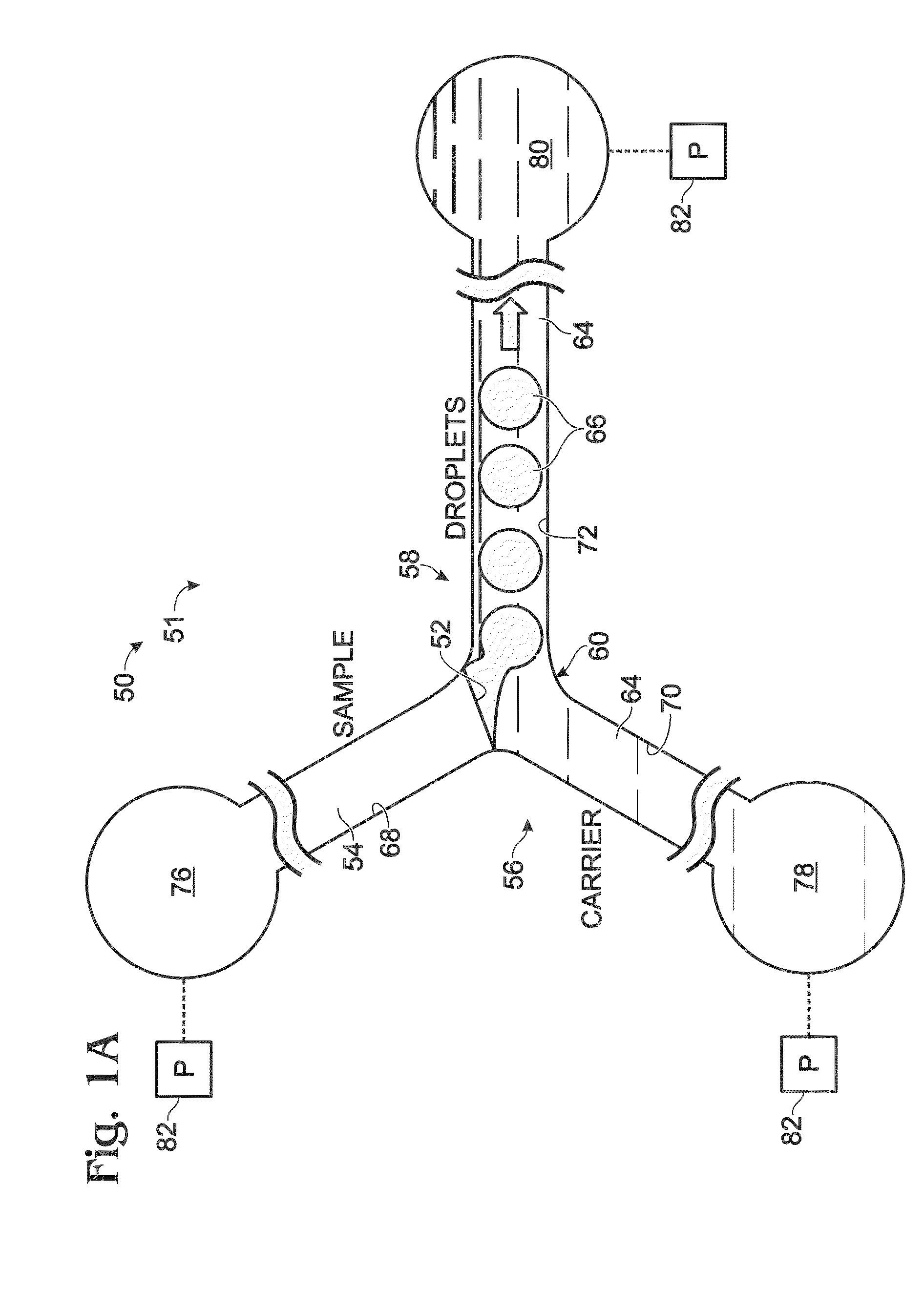
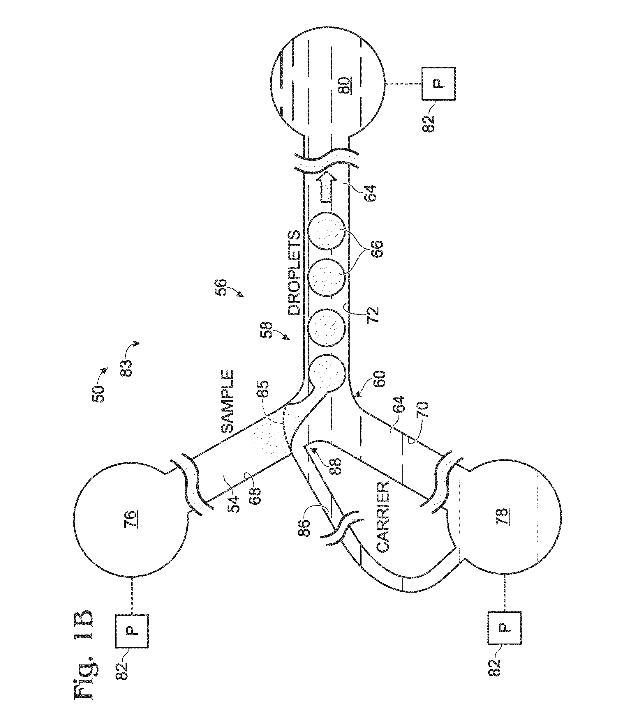
[0105]FIGS. 2 and 3 show an exemplary device 91 for droplet generation in system 50. Device 91 does not have any of the features described above in Sections I and II for sample positioning. However, any of the structure, components, and features of device 91 may be applicable to, and included in, any of the droplet generation devices described elsewhere herein. In FIG. 2, and in many of the drawings that follow, the term “oil” is used as an exemplary shorthand for “carrier,” and is not intended to limit the type of carrier fluid used.

[0106]Device 91 has a cross-shaped, planar arrangement of channels 68, 70a, 70b, and 72 that meet at channel junction 60 to create droplet generation region 58 (FIG. 2). Channel network 56...

example 2

Exemplary Wetting Boundary Formed by a Step

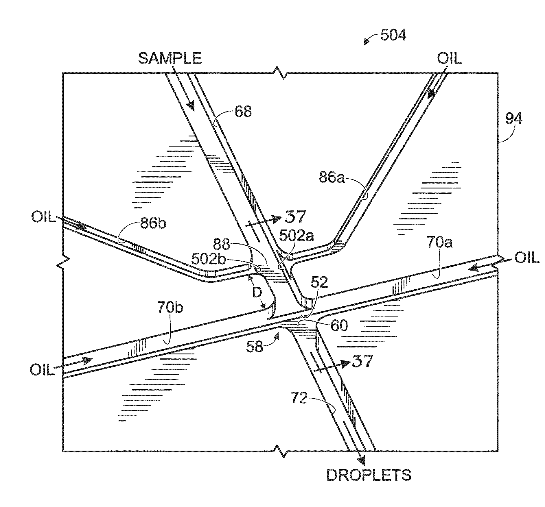
[0121]This example describes exemplary droplet generation devices having a wetting boundary formed by a step located at or upstream of a channel junction; see FIGS. 9-16. The devices of this example may have any suitable combination of the features disclosed elsewhere in the present disclosure, such as in Sections I and II and Example 1, among others, and / or in the patent documents listed above under Cross-References, which are incorporated herein by reference.

[0122]FIG. 9 shows a fragmentary, generally top view of an exemplary droplet generation device 130 having a step 52 produced by an abrupt change in the depth of channel network 56. (In this view, cap 96, which provides a ceiling of the channel network, has been removed to simplify the presentation.)

[0123]FIG. 10 shows a fragmentary sectional view of device 130. Step 52 may be formed at channel junction 60 and / or upstream of the channel junction in sample input channel 68. The step may...

example 3

Exemplary Patterned Wetting Boundary

[0129]This example describes exemplary droplet generation systems having a patterned wetting boundary formed by a series of laterally arranged ridges and / or grooves located near and / or at a channel junction; see FIGS. 17-27.

[0130]FIG. 17 shows a top view of an exemplary droplet generation device 250 having a micro-patterned wetting boundary 251. The wetting boundary is formed by a series of elongate surface features 252 defined by surface 97a of cap 96. Surface features 252 have sharp edges oriented transverse to the long axis of sample input channel 68 to restrict wicking of the sample across the surface features. The surface features may be at least generally parallel to carrier input channels 70a and 70b, to encourage the carrier fluid to wick along the surface features, thereby further preventing the sample from wicking into the channel junction.

[0131]Surface features 252 may provide a redundant wetting boundary for the sample. In other words,...


PUM

PropertyMeasurementUnit
Flow rateaaaaaaaaaa
Depthaaaaaaaaaa

Abstract

System, including methods and apparatus, for forming droplets of an emulsion. The system may include a channel junction at which a stream of sample fluid is divided into droplets by a dividing flow of carrier fluid. The system also may include one or more features configured to position sample fluid for reduced contact between the sample fluid and one or more surface regions of the channel junction, which may improve the consistency of droplet formation. In exemplary embodiments, sample fluid may be positioned by a step member produced by an increase in channel depth, and/or by directing flow of carrier fluid to form a barrier layer between sample fluid and a wall region, such as a ceiling region or floor region, of a channel network.

Description

CROSS-REFERENCES TO PRIORITY APPLICATIONS[0001]This application is based upon and claims the benefit under 35 U.S.C. §119(e) of U.S. Provisional Patent Application Ser. No. 61 / 674,516, filed Jul. 23, 2012, and U.S. Provisional Patent Application Ser. No. 61 / 759,775, filed Feb. 1, 2013, each of which is incorporated herein by reference in its entirety for all purposes.CROSS-REFERENCES TO OTHER MATERIALS[0002]This application incorporates by reference in their entireties for all purposes the following patent documents: U.S. Pat. No. 7,041,481, issued May 9, 2006; U.S. Patent Application Publication No. 2010 / 0173394 A1, published Jul. 8, 2010; U.S. Patent Application Publication No. 2011 / 0217712 A1, published Sep. 8, 2011; U.S. Patent Application Publication No. 2012 / 0152369 A1, published Jun. 21 2012; U.S. Patent Application Publication No. 2012 / 0190032 A1, published Jul. 26, 2012; U.S. Provisional Patent Application Ser. No. 61 / 813,137, filed Apr. 17, 2013; and U.S. Provisional Paten...

Claims


Application Information

Patent Timeline
IPC IPC(8): G01N1/28
CPCG01N1/28B01L3/502784B01L2300/0816B01L2300/0867B01L2400/0487B01L2400/084Y10T436/25B01F23/41B01F33/3011
Inventor CAULEY, III, THOMAS H.BRACKBILL, TIMOTHYBOUSSE, LUCPETERSEN, JON
Owner BIO RAD LAB INC
Why Eureka
Try Eureka