
Road shape estimating system

a technology of estimating system and road shape, applied in vehicle position/course/altitude control, process and machine control, instruments, etc., can solve the problems of insufficient position detection accuracy, inability to achieve the achievable position accuracy, and insufficient function of gps position detection accuracy, etc., to achieve the effect of estimating the curve shape of the road more simply and more accurately

Inactive Publication Date: 2014-01-23
TOYOTA JIDOSHA KK
View PDF4 Cites 3 Cited by
  • Summary
  • Abstract
  • Description
  • Claims
  • Application Information

AI Technical Summary

Benefits of technology

The patent allows for easier and more accurate estimation of the shape of a road curve.

Problems solved by technology

However, when only a navigation system is used in order to accurately recognize the road shape, there is a problem in terms of achievable positional accuracy.
In the case of the above described technique, however, the car navigation system is used as means for estimating the road shape, thus there is a disadvantage in that its function ceases when the GPS reception is shut off (shadowing).
Further, in some cases, the position detection accuracy of GPS is not sufficient.
Furthermore, there is a disadvantage in that the number of node points increases or the control logic becomes complicated in order to improve the calculation accuracy of the radius of curvature.
Moreover, there is a disadvantage in that when a plurality of roads exists in the vicinity, any mismatches may be caused.
Additionally, since the navigation system itself is expensive, there is a case where a large amount of development cost is required in order to overcome the disadvantages as described above.
However, because this technique is disadvantageous in that: detectable stationary objects are limited depending on the material or the shape of the road side obstacles, its weather robustness is low and a possibility of misestimation increases in complicatedly-shaped roads or complicated environment (including passing persons and bicycles on the road side), it has been difficult to estimate the radius of curvature of the curve more simply and accurately.

Method used


Image

  • Road shape estimating system
  • Road shape estimating system
  • Road shape estimating system

Examples


first example

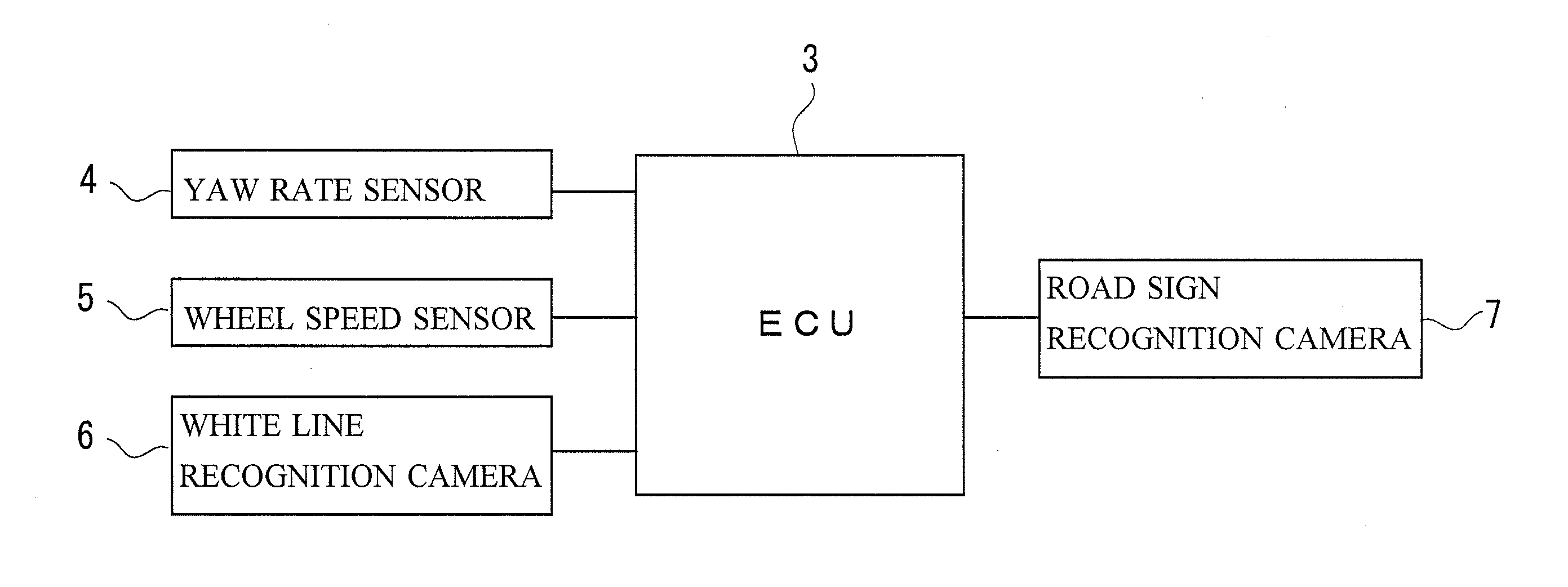
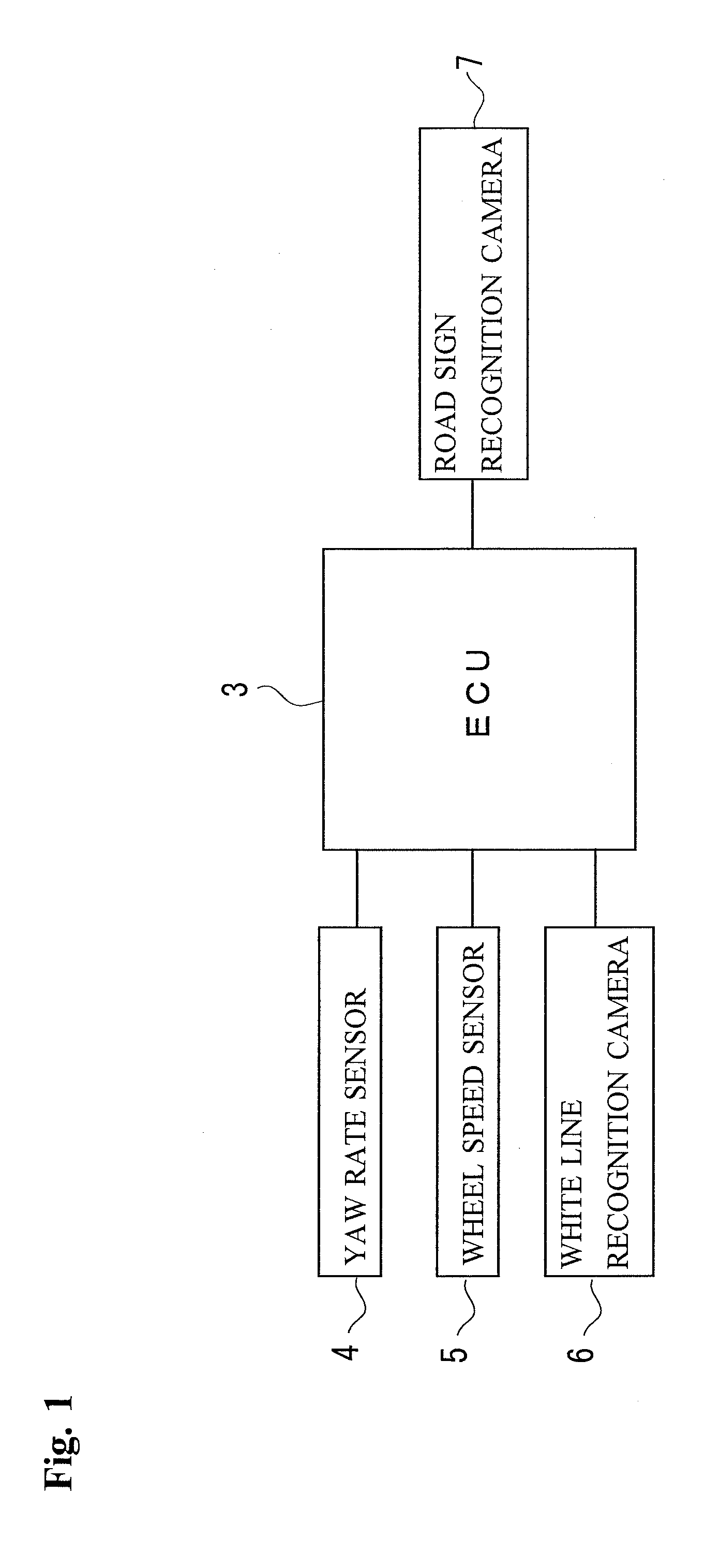
[0033]FIG. 1 is a block diagram illustrating a schematic arrangement of a road shape estimating system according to this example. This system is provided with ECU 3 which is an electronic control computer for controlling an internal combustion engine. The ECU 3 is provided with, for example, unillustrated ROM, RAM, CPU, an input port, and an output port, to which a yaw rate sensor 4, a wheel speed sensor 5, a white line recognition camera 6 and a road sign recognition camera 7 are electrically connected. Here, at least the yaw rate sensor 4, the wheel speed sensor 5 and the white line recognition camera 6 correspond to the moving object information sensor(s) according to this example. Further, the white line recognition camera 6 also constitutes the white line image acquiring device according to this example.

[0034]A detection signal corresponding to a vehicle yaw rate is provided from the yaw rate sensor 4 to the ECU 3, and a wheel speed pulse synchronized with the rotation of the w...


PUM


Abstract

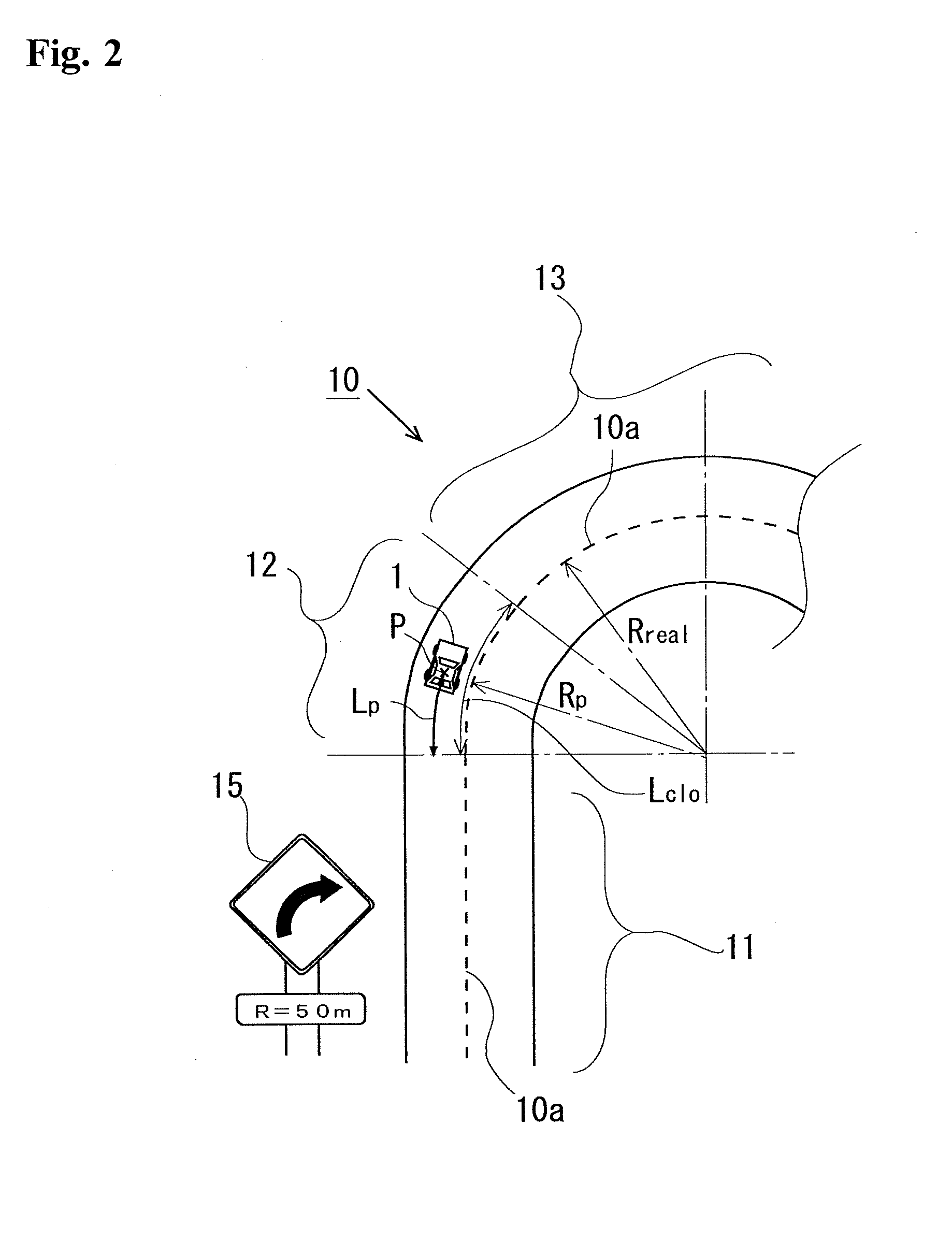
A technique, which makes it possible to estimate a curve shape of a road more simply and more accurately, is provided. Disclosed is a road shape estimating system for estimating the shape of the road including a curve easement section in which a radius of curvature changes according to a clothoid curve and a circular curve section in which a radius of curvature is constant. The distance Lp from a curve starting point and the radius of curvature Rp of the curve at a vehicle position in the curve easement section, are determined on the basis of the information from a white line recognition camera of the vehicle, a yaw rate sensor and a wheel speed sensor, and the radius of curvature Rreal of the circular curve section is determined from an image of a road sign recognition camera. Then, the length Lclo of the curve easement section is derived by using the information as described above and a clothoid function to estimate the shape of the road.

Description

TECHNICAL FIELD[0001]The present invention relates to a road shape estimating system for estimating a shape of a road on which a moving object such as an automobile or the like moves, the road having a curvature variation section in which a radius of curvature changes in accordance with a predetermined function and a curvature fixed section in which a radius of curvature is constant.BACKGROUND ART[0002]In systems such as Curve Speed Warning System (CSWS), Auto Cruise Control (ACC), Lane Keeping Assist System (LKA) and Pre-Crash Safety (PCS), improving the convenience, the safety and the fuel efficiency is demanded. For this purpose, it is required that the accuracy of control be improved, and therefore, for example, it is needed that a road shape, such as a curve shape, be accurately recognized. However, when only a navigation system is used in order to accurately recognize the road shape, there is a problem in terms of achievable positional accuracy. Thus, in this case, in order to...

Claims


Application Information

Patent Timeline
Patent Type & Authority Applications(United States)
IPC IPC(8): B60R99/00
CPCB60R99/00B60W30/12B60W40/072G08G1/167B60W2552/30B60W2555/60B60W2420/403
Inventor YOSHIHAMA, YUKI
Owner TOYOTA JIDOSHA KK
Learn More