Aircraft engine

Active Publication Date: 2014-01-30
KAWASAKI HEAVY IND LTD
View PDF7 Cites 6 Cited by
  • Summary
  • Abstract
  • Description
  • Claims
  • Application Information

AI Technical Summary

Benefits of technology

The present invention relates to an aircraft engine where an accessory can be directly supported by the engine main body without an accessory gearbox. This helps to prevent an increase in the size of the engine and reduces the overall weight, cost, and air resistance. The accessory is connected to the mounting pad of the engine main body through a take-out shaft, which is driven by the engine rotary shaft. The connection is firm even when the accessory is increased in size, and there is no risk of foreign substances entering the engine main body through the opening. The use of a bolt and nut facilitates a secure and easy connection between the mounting pad and the accessory flange. The take-out shaft can be splined to the input shaft of the accessory, making it easy to connect or separate.

Problems solved by technology

It has, however, been found that the accessory to be fitted to the aircraft engine in recent years is increasing in size, which in turn leads to an increase in size of the accessory gearbox for use in supporting the accessory.
In addition to the increase in size of the accessory, where the number of accessories to be fitted increases, the accessory gearbox used to support those accessories is, too, increased in size, and this will in turn results in the increase of the overall weight of the aircraft engine as well as the increase of the cost and the air resistance.

Method used


Image

  • Aircraft engine
  • Aircraft engine
  • Aircraft engine

Examples


Embodiment Construction

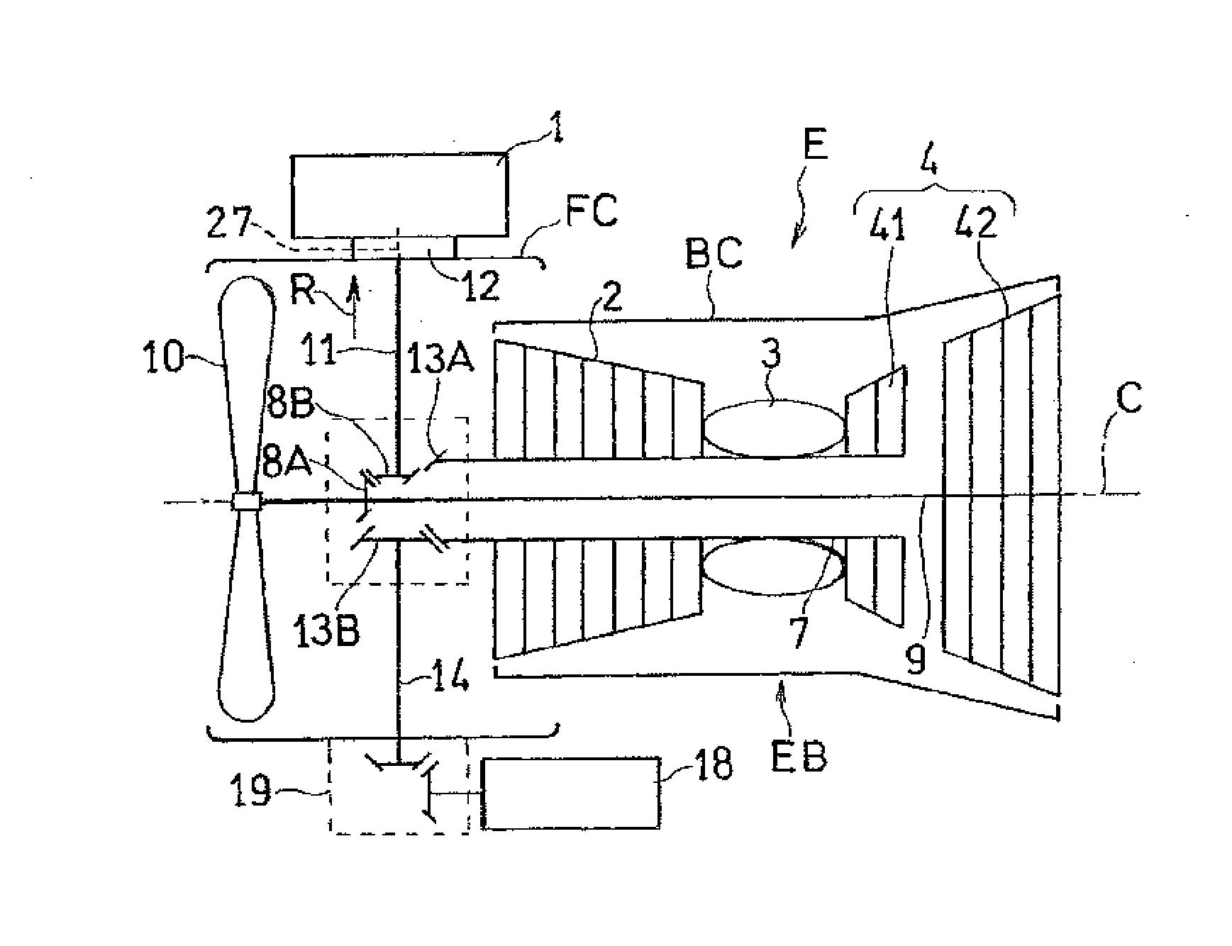
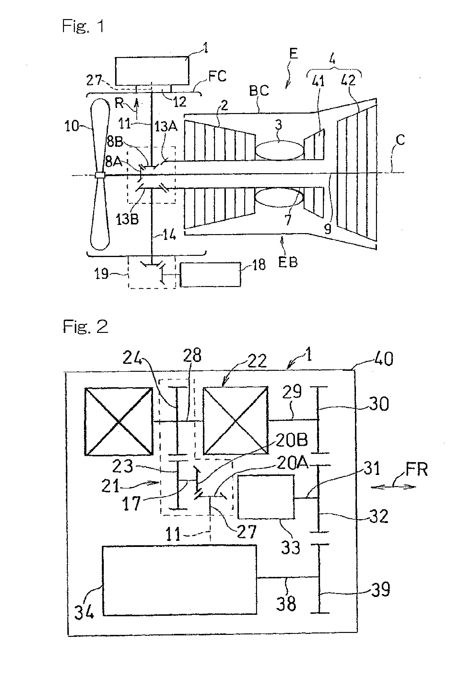
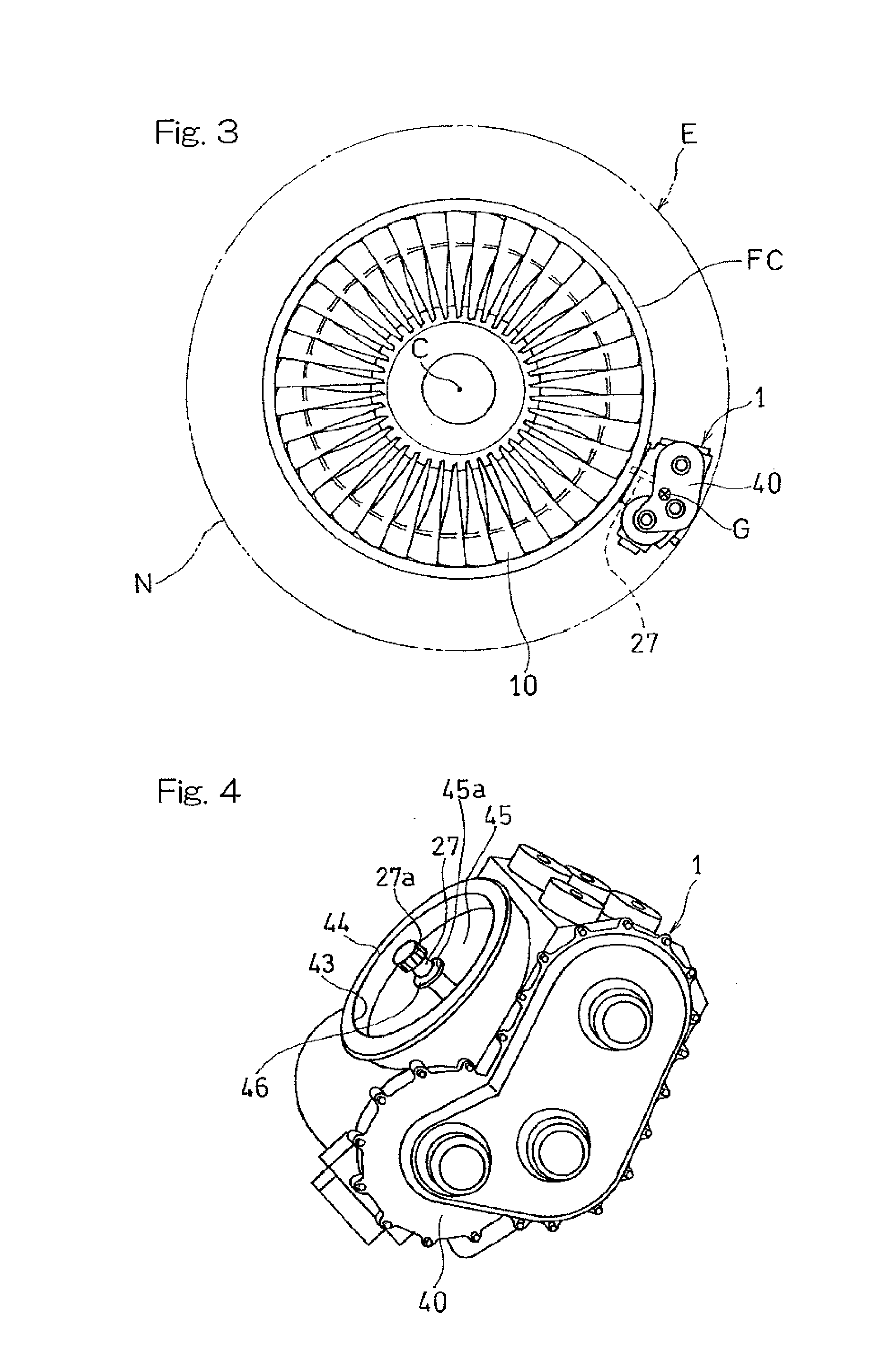
[0029]Hereinafter, preferred embodiments of the present invention will be described in detail with particular reference to the accompanying drawings. In particular, FIG. 1 pertains to the first preferred embodiment of the present invention and illustrates a schematic structural diagram showing the manner of connection of an electric power generating device 1, which is one of accessories for an aircraft engine E. The aircraft engine E shown therein is a two shaft type or a double shaft type fan engine of a kind including a high pressure shaft 7 and a low pressure shaft 9 that are used as rotary drive shafts of the engine E. A engine main body EB thereof includes a compressor 2, a combustor 3, a turbine 4 and a fan 10 as principal component parts and also includes a main body casing BC for enclosing the compressor 2, the combustor 3 and the turbine 4, and a fan casing FC for enclosing the fan 10. A compressed air supplied from the compressor 2 is, after having been mixed with fuel, bu...


PUM


Abstract

To provide an aircraft engine in which an accessory can be directly supported with no accessory gearbox intervening to thereby suppress an increase in size thereof, the aircraft engine (E) includes a take-out shaft (11) having a first end portion, connected with an engine rotary shaft (9) and extending in a radially outward direction, and also having a second end portion connected with an accessory (1), and a mounting pad (12) provided in an engine main body (EB) and to which the accessory (1) is fitted. The mounting pad (12) forms an outer perimeter of an opening (48) through which the take-out shaft (11) extends. The opening (48) is sealed by a covering (47), through which the take-out shaft (1) extends, and a sealing member (49) to seal between the covering (47) and the take-out shaft (11).

Description

CROSS REFERENCE TO THE RELATED APPLICATION[0001]This application is based on and claims Convention priority to Japanese patent application No. 2011-085428, filed Apr. 7, 2011, the entire disclosure of which is herein incorporated by reference as a part of this application.BACKGROUND OF THE INVENTION[0002]1. Field of the Invention[0003]The present invention relates to an engine for aircrafts, which is of a type equipped with an accessory that is driven by an engine rotary shaft.[0004]2. Description of Related Art[0005]An accessory or auxiliary equipment such as, for example, an electric power generator or any of various pumps, which is used in association with an aircraft is supported by an engine main body through an accessory gearbox (AGB) and is driven by an engine rotary shaft through gears in the accessory gearbox coupled with the engine rotary shaft. In this respect, see the patent documents 1 and 2 listed below.PRIOR ART LITERATURE[0006][Patent Document 1] U.S. Pat. No. 7,386,...

Claims


Application Information

Patent Timeline
IPC IPC(8): F02C7/32
CPCF02C7/32F02C7/36F05D2270/304F05D2270/024F02C7/275F05D2260/532F05D2260/4031Y02T50/60F16H15/00
Inventor GOI, TATSUHIKOTANAKA, KENICHIROWATANABE, KOJIFUJII, ISAO
Owner KAWASAKI HEAVY IND LTD
Why Eureka
Try Eureka