Digital binder printing

a binder printing and digital technology, applied in the direction of printing processes, duplicating/marking methods, coatings, etc., can solve the problems of cost efficiency only in very large production volumes, complicated production process, and more difficult to create designs, wood decors, etc., and achieve cost efficiency

Active Publication Date: 2014-01-30
CERALOC INNOVATION AB
View PDF11 Cites 75 Cited by
  • Summary
  • Abstract
  • Description
  • Claims
  • Application Information

AI Technical Summary

Benefits of technology

[0098]The production method and equipment according to embodiments of the invention make it possible to produce very advanced decorative patterns in a flexible and very cost efficient way since the digital equipment is only used to create a pattern with a binder that does not have any colour pigments.

Problems solved by technology

The production process is rather complicated and is only cost efficient in very large production volumes.
It is however more difficult to create designs such as, for example, wood decors.
However the volumes are still very small mainly due to the high cost of the ink and the high investment cost for the industrial printers.
Such printers are slow but one small print head can generate a bigger image.
However a part print is not as flexible as a full print since the base colours are more difficult to change than when a full print is used.
This is difficult particularly at the low viscosities that are required for a good functioning of the print heads.
Pigments have a natural tendency to settle out and fall down in the liquid carrier.
Colour pigments as such are rather cost competitive but the production of pigment based inks and other inks for digital printers is very complicated and expensive and this results in a very high cost for the ink that normally may be in the region of about 100 EUR / litre.
As summary it may be mentioned that digital printing is a very flexible method but it cannot be fully utilized due to the high cost for the ink.
The costs are primarily caused by the need to mill down the colour pigments to well-defined very small particles and to disperse the particles throughout the carrier fluid.
However, the other aspects of the technology, mainly related to the possibility to apply a liquid substance very precisely with a non-impact method, have not been fully utilized or developed.

Method used


Image

  • Digital binder printing
  • Digital binder printing
  • Digital binder printing

Examples


example

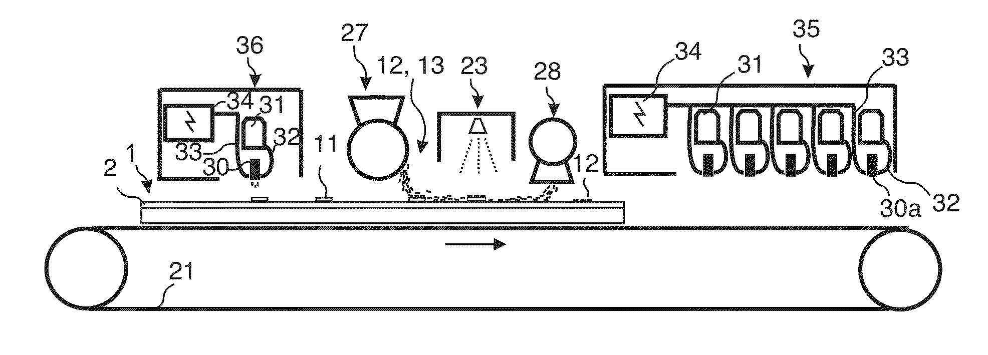
[0142]A powder mix of 300 g / m2 comprising wood fibres, melamine formaldehyde particles, brown colour pigments and aluminium oxide particles such as corundum was applied by scattering equipment on an 8 mm HDF core. The mix was sprayed with deionized water and dried by an UV oven such that a hard stabilized powder based surface with a brown basic colour was obtained. The panel with the stabilized powder surface was put on a conveyer and displaced under a digital Piezo coating head that applied drops of water on the stabilized surface and that printed a transparent wood grain pattern on the surface. The melamine formaldehyde under the transparent pattern melted when the digital coating Piezo head applied the water drops. Black pigments were in a second step scattered over the whole surface and the transparent pattern. The panel was thereafter displaced by a conveyor under an UV oven. The melamine formaldehyde in the transparent pattern was dried again and the pigments above the transpa...


PUM

PropertyMeasurementUnit
thickaaaaaaaaaa
thickaaaaaaaaaa
widthaaaaaaaaaa

Abstract

A method and equipment to form a digital image on a surface by applying a powder layer including colour pigments on the surfaces, bonding a part of the powder and removing the non-bonded powder from the surface.

Description

CROSS REFERENCE TO RELATED APPLICATIONS[0001]The present application claims the benefit of U.S. Provisional Application No. 61 / 675,971, filed on Jul. 26, 2012. The entire contents of U.S. Provisional Application No. 61 / 675,971 are hereby incorporated herein by reference in their entirety.TECHNICAL FIELD[0002]The disclosure generally relates to the field of digitally created decorative surfaces preferably building panels such as floor and wall panels. The disclosure relates to methods and equipment to produce such decorative surfaces.FIELD OF APPLICATION[0003]Embodiments of the present invention are particularly suitable for use in floors, which may be formed of floor panels comprising a core, a decorative layer and a transparent wear resistant structured layer above the decorative layer. The following description of technique, problems of known technology and objects and features of embodiments of the invention will therefore, as a non-restrictive example, be aimed above all at this...

Claims


Application Information

Patent Timeline
Patent Type & Authority Applications(United States)
IPC IPC(8): B41J2/485
CPCB41J2/485B05D1/12B05D1/36B05D3/067B05D5/06B05D7/06B05D2401/32B41J3/407B41M3/06B41M5/0047B41M5/0052B41M5/0064B41M5/0076B41M7/0081B41M7/009B41J11/00214E04F15/102
Inventor PERVAN, DARKO
Owner CERALOC INNOVATION AB
Why Eureka
Try Eureka