
Image capturing lens and image capturing apparatus

a technology of image capturing and image capturing apparatus, applied in the field of image capturing lenses, can solve the problems of reducing the resolving power, unable to obtain the desired resolving power, and the difficulty of obtaining sufficient brightness of the image capturing lens using the five lenses described above, so as to reduce the overall optical length

Inactive Publication Date: 2014-01-30
TIANJIN OFILM OPTO ELECTRONICS CO LTD
View PDF5 Cites 22 Cited by
  • Summary
  • Abstract
  • Description
  • Claims
  • Application Information

AI Technical Summary

Benefits of technology

The conditional expression (4a) relates to the ratio of the combined focal length of two lenses to the focal length of the entire lens system. It defines a desirable range for securing back focus while minimizing distortion. If the image capturing lens falls below the lower limit, it cannot properly secure back focus and causes distortion. On the other hand, if the lens exceeds the upper limit, it causes the back focus to become too long, making it difficult to reduce the overall optical length. The conditional expression (4b) improves the reliability of the lower and upper limits, and the expression (4c) further improves the reliability of the lower and upper limits. Additionally, the conditional expression (5a) defines the range of ratio of the overall optical length to the focal length of the entire lens system.

Problems solved by technology

However, the image capturing lenses that use five lenses described above are difficult to obtain sufficient brightness because the resolving power is reduced if trying to increase the aperture to get sufficient brightness (for example, the image capturing lens of Patent Document 1 or the like is premised on an F-number of around 2.8).
Further, in the five element image capturing lenses described above, if trying to reduce the thickness (reduce the overall optical length), inhibition of various aberrations (e.g., chromatic aberration and distortion) becomes difficult, thereby causing a problem that a desired resolving power may not be obtained.

Method used


Image

  • Image capturing lens and image capturing apparatus
  • Image capturing lens and image capturing apparatus
  • Image capturing lens and image capturing apparatus

Examples


specific examples

[0144]Specific examples of the image capturing lens according to the present embodiment will be described collectively.

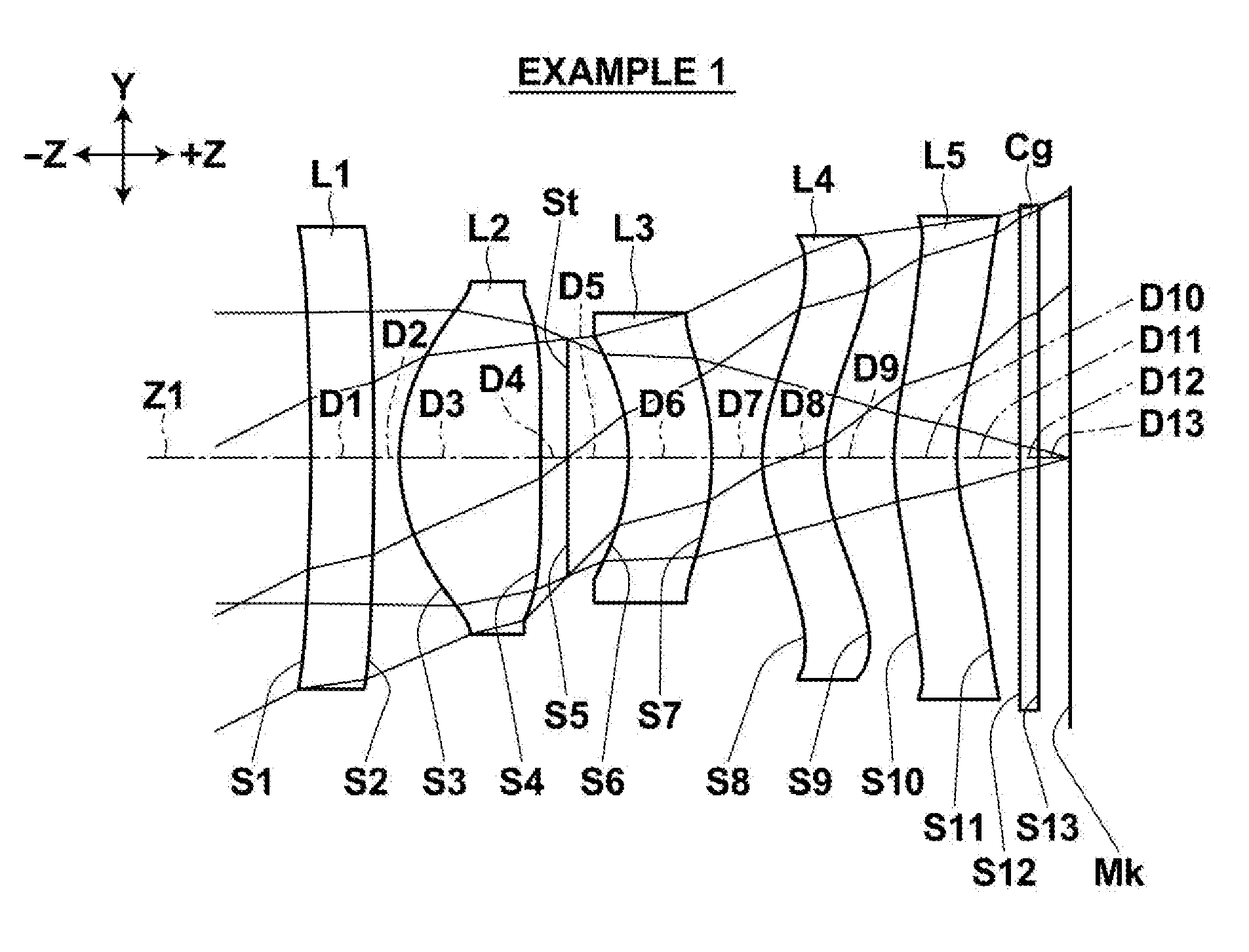
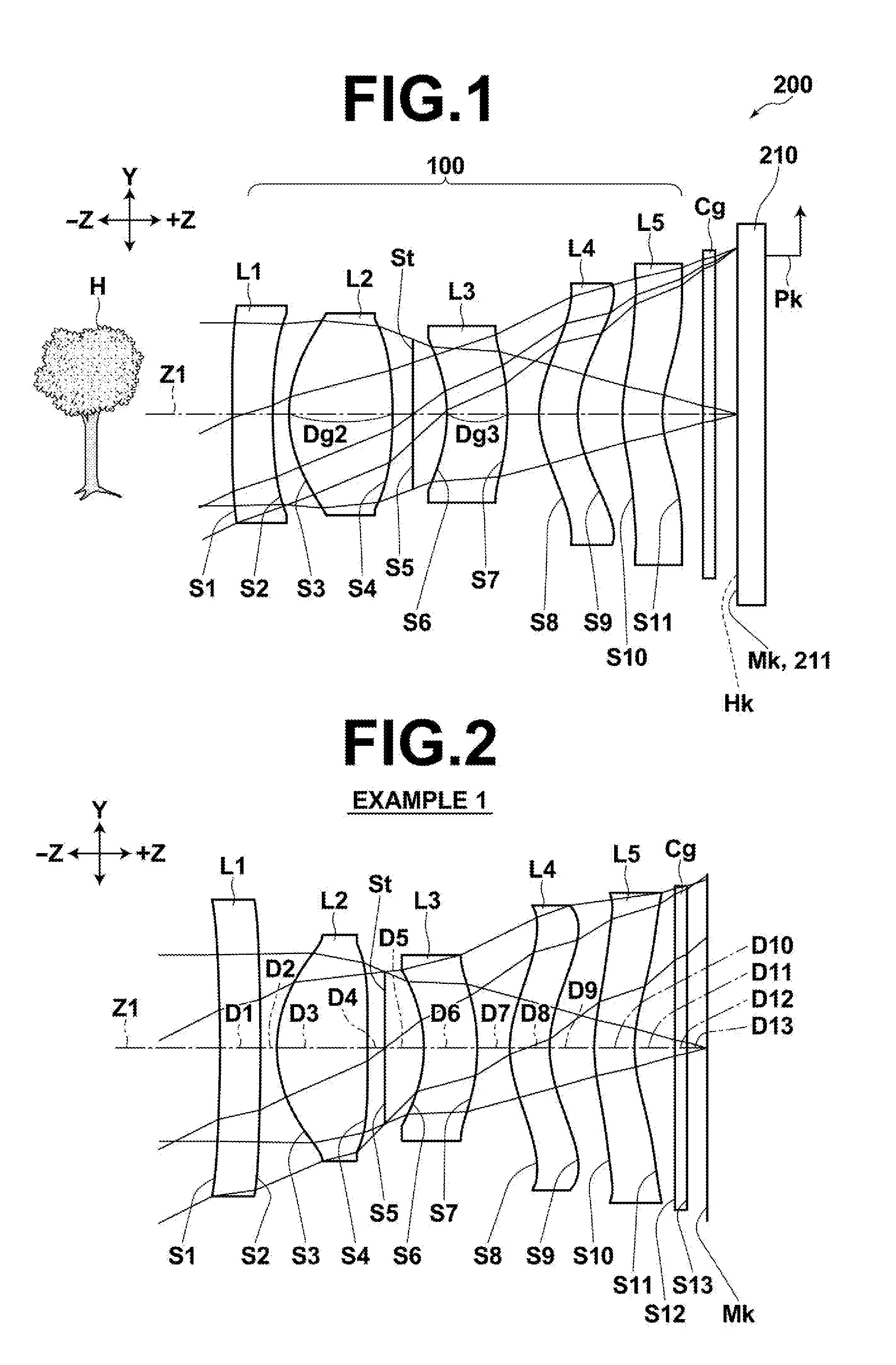
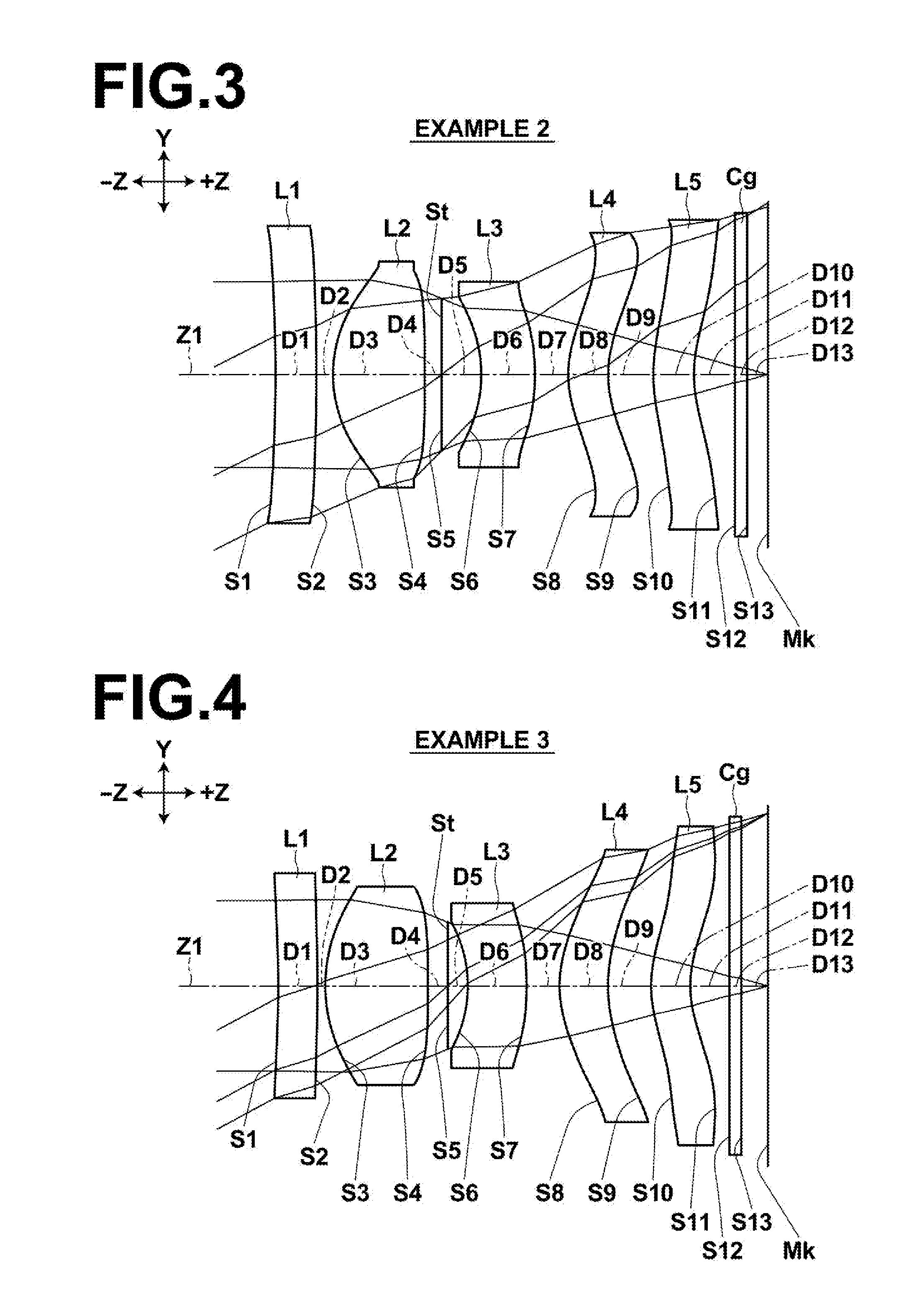
[0145]FIGS. 2 to 13 illustrate cross-sections of image capturing lenses corresponding to Examples 1 to 12 respectively.

[0146]In FIGS. 2 to 13, the symbol Lj represents jth lens in which a number j is given to each lens in a serially increasing manner toward the image side (image forming side) with the most object side lens being taken as the first lens. The symbol Si represents ith surface (which includes aperture stop and the like) in which a number is given to each surface in a serially increasing manner toward the image side (image forming side) with the object side surface of the most object side lens being taken as the first surface. The symbol Di represents the distance between ith surface and (i+1)th surface on the optical axis.

[0147]Components of image capturing lenses of Examples 1 to 12 shown in FIGS. 2 to 13 identical to those of the image capturing lens ...


PUM


Abstract

Arranging a negative first lens, a positive second lens, a negative third lens, a positive fourth lens, and a negative fifth lens from the object side, in which the image side surface of the fifth lens has an aspherical shape with one or more inflection points and a concave shape toward the image side in a paraxial region, and, when the focal length of the entire lens system, radius of curvature of the image side surface of the first lens, radius of curvature of the image side surface of the second lens, overall optical length, focal length of jth lens, and Abbe number of jth lens are taken as f, R2, R4, TL, fj, and vj respectively, the image capturing lens is configured to simultaneously satisfy conditional expressions (1a): −1.5<f / R2<1.6, (2a): −1.6<f / R4<0.05, (3a): 0.95≦f4 / f≦4.3, (5a): 1.0≦TL / f≦2.2, and (12b): −2.0<Σ(fj / νj) / f<0.5.

Description

CROSS REFERENCE TO RELATED APPLICATIONS[0001]This application is a Bypass continuation of PCT / JP2010 / 002192 filed on Mar. 29, 2012, which claims priority to Japanese Application Nos. 2011-076179 filed on Mar. 30, 2011 and 2012-069526 filed on Mar. 26, 2012. The entire contents of each of the above applications are hereby incorporated by reference.TECHNICAL FIELD[0002]The present invention relates to an image capturing lens for forming an optical image of a subject on an image sensor, such as a CCD (Charge Coupled Device), CMOS (Complementary Metal Oxide Semiconductor), or the like, and an image capturing apparatus provided with the image capturing lens to perform image capturing, such as a digital still camera, camera-equipped cell phone, personal digital assistance (PDA), smartphone, or the like.BACKGROUND ART[0003]Recently, along with the spread of personal computers to homes and the like, digital still cameras capable of inputting image information obtained by imaging a landscape...

Claims


Application Information

Patent Timeline
Patent Type & Authority Applications(United States)
IPC IPC(8): G02B13/18
CPCG02B13/18G02B13/0045
Inventor NODA, TAKAYUKI
Owner TIANJIN OFILM OPTO ELECTRONICS CO LTD
Learn More