Method and circuit for controlling a switching regulator

Active Publication Date: 2014-01-30
STMICROELECTRONICS INT NV
View PDF4 Cites 57 Cited by
  • Summary
  • Abstract
  • Description
  • Claims
  • Application Information

AI Technical Summary

Benefits of technology

[0040]When the sampled value of the control voltage VCSref is within the band BV the first counter stays unchanged, and when the sampled value is below the first value VFBZL the first counter is increased by one, but if it

Problems solved by technology

Although the solutions outlined above achieve their purpose and are ad

Method used


Image

  • Method and circuit for controlling a switching regulator
  • Method and circuit for controlling a switching regulator
  • Method and circuit for controlling a switching regulator

Examples


Embodiment Construction

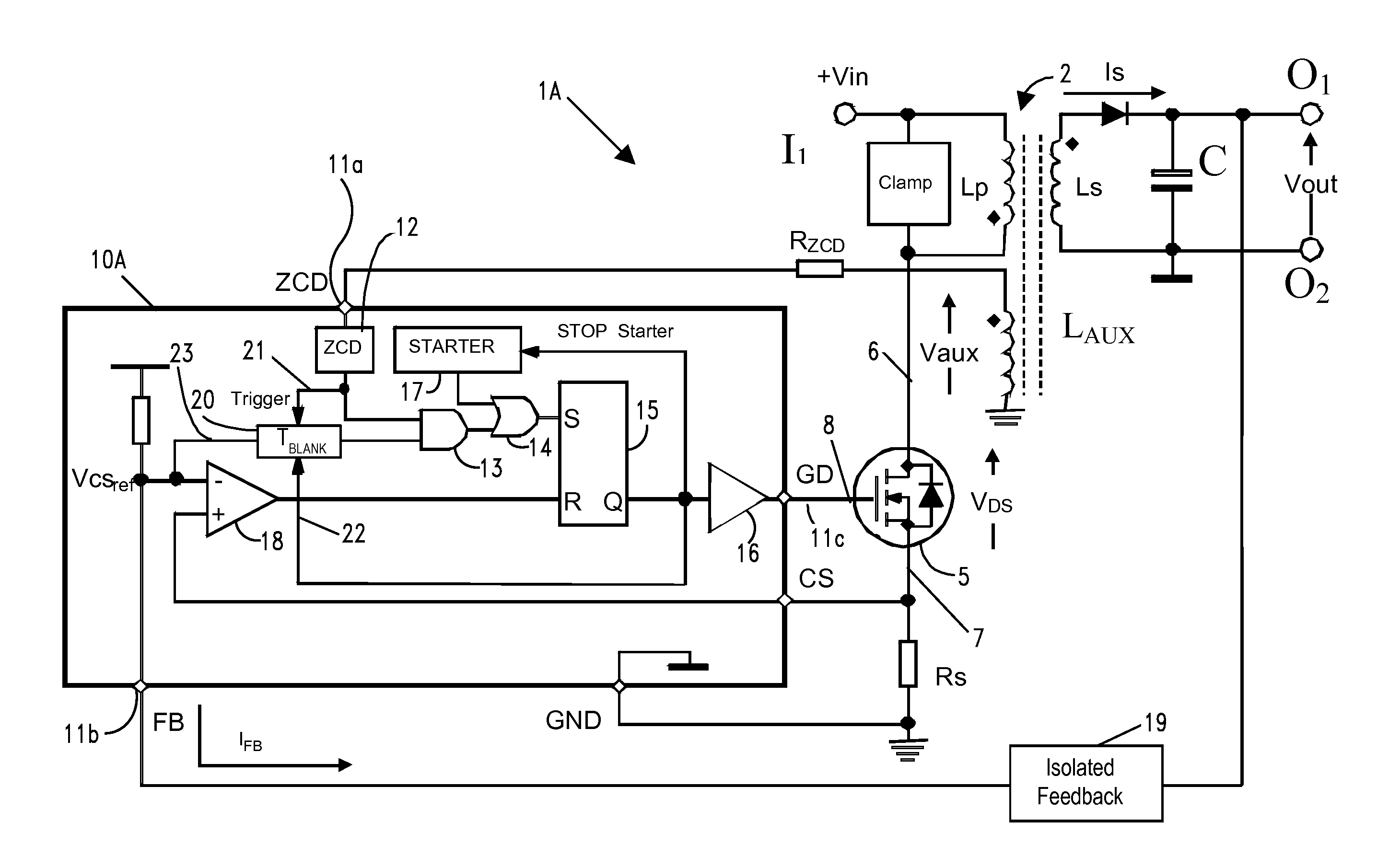
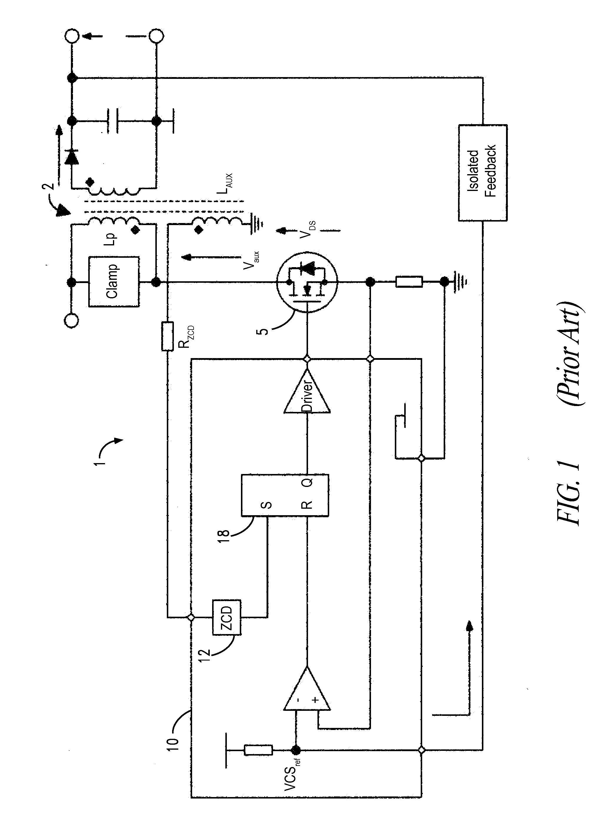
[0059]FIG. 8 shows the flow diagram of a method, according to one embodiment of the present invention, for controlling a switching regulator 1A, shown in FIG. 9A, that is similar to the switching regulator 1 represented in FIG. 1 and described above, for which parts and details having the same structure and function will be indicated with the same reference numerals and letters.

[0060]As shown in FIG. 9A, the switching regulator 1A comprises a transformer 2 coupled with and controlled by a switch 5.

[0061]The transformer 2 comprises a primary winding Lp connected to an input terminal I1 of the switching regulator 1 and a secondary winding Ls arranged between the output terminals O1, O2.

[0062]The switch 5 is arranged in series with the primary winding Lp and coupled with a reference voltage VGND that in an embodiment is the ground voltage.

[0063]The switch 5 is alternately driven in conduction status and in interdiction status by a PWM control signal VGD to control the transformer 2 in ...


PUM


Abstract

A method for controlling a switching regulator includes defining a waiting time during which a trigger signal corresponding to a recirculation signal of the switching regulator is ignored holding a control switch in an open condition, and detecting a number of local valleys of the recirculation signal during the waiting time. In particular, defining the waiting time is performed for each switching cycle by adding a first value, which is determined on the basis of a load on the regulator, to a second variable value, which is proportional to the number valleys detected during the waiting time of the preceding switching cycle.

Description

BACKGROUND[0001]1. Technical Field[0002]The present disclosure relates to a method for controlling a switching regulator.[0003]The present disclosure also relates to a control circuit for a switching regulator.[0004]The disclosure concerns in particular, but not exclusively, a method and a circuit for controlling a switching regulator of the quasi-resonant flyback type and the following description is made with reference to this specific field of application with the sole purpose of simplifying its presentation.[0005]2. Description of the Related Art[0006]Switching regulators are used in power supply systems to provide a constant voltage or current in output as the supply voltage varies and as the load applied to the output terminals varies. The quasi-resonant (QR) flyback switching regulator is a regulator with an insulation arranged between the input terminals and the output terminals made from a magnetizable part, for example a transformer, which is magnetized and demagnetized th...

Claims


Application Information

Patent Timeline
IPC IPC(8): H02M3/335
CPCH02M3/33507H02M3/33515H02M3/33523Y02B70/10H02M3/335H02M3/315
Inventor ADRAGNA, CLAUDIO
Owner STMICROELECTRONICS INT NV
Why Eureka
Try Eureka