
Closed loop cooling system for a gas turbine

a closed loop cooling and gas turbine technology, applied in the direction of machines/engines, stators, liquid fuel engines, etc., can solve the problems of reducing the heat removal capability of the extracted air, reducing the volume of combustion gases, and reducing the overall efficiency and output of the gas turbin

Active Publication Date: 2014-01-30
GENERAL ELECTRIC CO
View PDF8 Cites 25 Cited by
  • Summary
  • Abstract
  • Description
  • Claims
  • Application Information

AI Technical Summary

Benefits of technology

The present invention provides systems for removing heat from a gas turbine. The systems include a plurality of stationary nozzles that have a cooling passage and a closed loop cooling coil that flows through the cooling coil and out of the gas turbine to remove heat. The cooling coil is positioned between the inlet of the cooling passage and the outer casing of the gas turbine. Cooling media flow through the cooling coil and out of the gas turbine to cool the gas turbine. These systems help improve the efficiency of the gas turbine by reducing the temperature of the working fluid.

Problems solved by technology

However, higher temperature combustion gases may produce excessive temperatures in the turbine that can approach or exceed the melting temperature of various turbine components.
However, the air extracted from the compressor has already been compressed, and thus heated, by some amount, thereby reducing the heat removal capability of the extracted air.
In addition, since the extracted air bypasses the combustors, extracting air from the compressor reduces the volume of combustion gases and overall efficiency and output of the gas turbine.
However, the elevated temperature of the compressed working fluid available for cooling generally limits the rate of heat transfer between the compressed working fluid and the walls of the internal passages.
However, these methods may create problems with oxidization within the gas turbine and may reduce overall plant efficiency.

Method used


Image

  • Closed loop cooling system for a gas turbine
  • Closed loop cooling system for a gas turbine
  • Closed loop cooling system for a gas turbine

Examples


Embodiment Construction

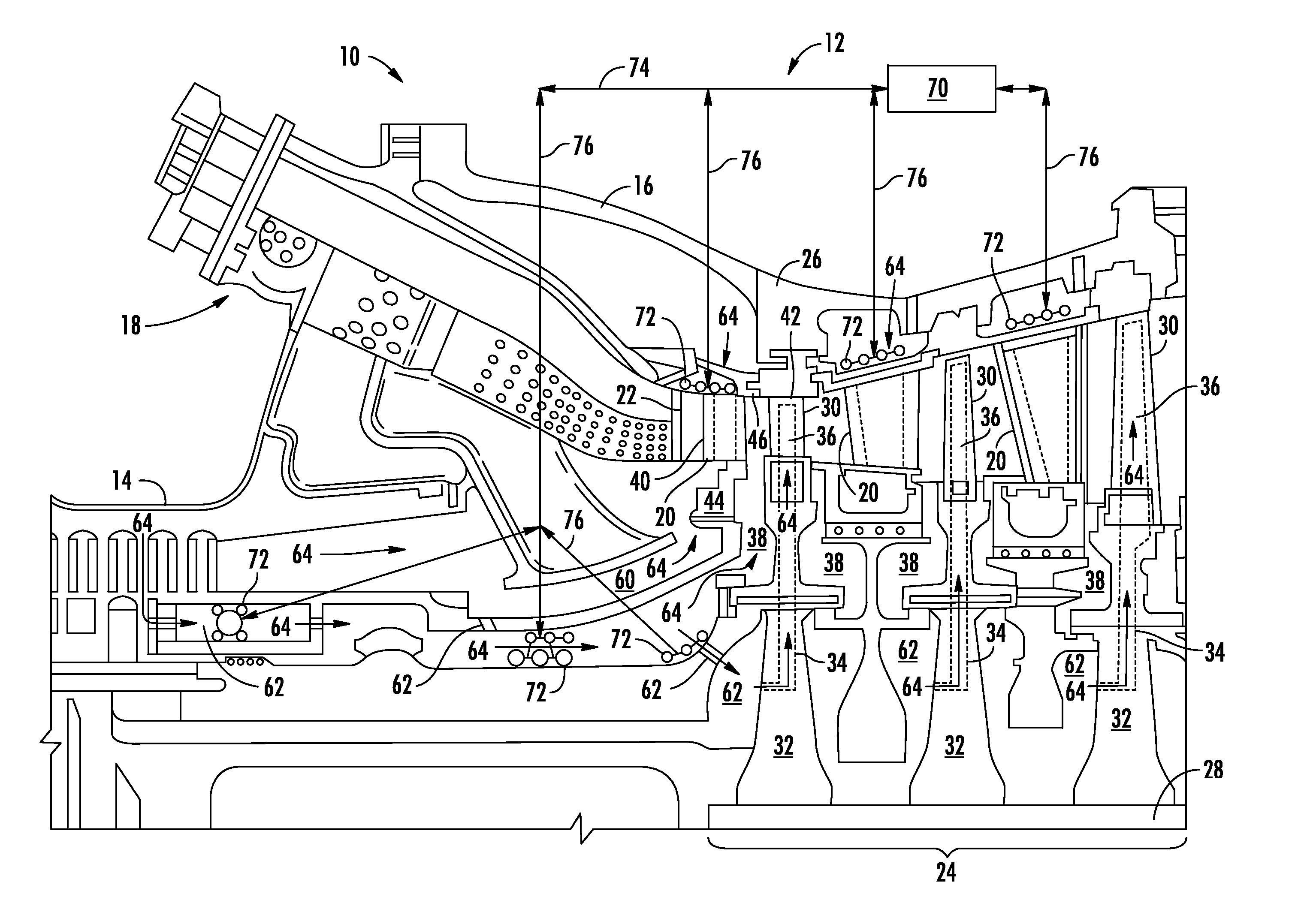
[0020]Reference will now be made in detail to present embodiments of the invention, one or more examples of which are illustrated in the accompanying drawings. The detailed description uses numerical and letter designations to refer to features in the drawings. Like or similar designations in the drawings and description have been used to refer to like or similar parts of the invention. As used herein, the terms “first”, “second”, and “third” may be used interchangeably to distinguish one component from another and are not intended to signify location or importance of the individual components. In addition, the terms “upstream” and “downstream” refer to the relative location of components in a fluid pathway. For example, component A is upstream from component B if a fluid flows from component A to component B. Conversely, component B is downstream from component A if component B receives a fluid flow from component A.

[0021]Each example is provided by way of explanation of the invent...


PUM


Abstract

A system for removing heat from a gas turbine generally includes a plurality of stationary nozzles arranged in an annular array within the gas turbine. Each of the plurality of stationary nozzles may include a radially outer platform and a radially extending cooling passage. The radially extending cooling passage may have an inlet that extends generally axially and circumferentially across a portion of the radially outer platform. A closed loop cooling coil may extend continuously circumferentially around the radially outer platform of two or more of the plurality of stationary nozzles. The closed loop cooling coil may be disposed circumferentially across and outside of the inlet of the radially extending cooling passage of each of the two or more stationary nozzles, and a cooling medium may flow through the cooling coil and out of the gas turbine so as to remove heat from the gas turbine.

Description

FIELD OF THE INVENTION[0001]The present invention generally involves a closed loop cooling system for a gas turbine.BACKGROUND OF THE INVENTION[0002]Gas turbines are widely used in commercial operations for power generation. A typical gas turbine includes a compressor, one or more combustors downstream from the compressor, and a turbine downstream from the one or more combustors. A working fluid such as air flows through an inlet of the compressor wherein the compressor imparts kinetic energy to the working fluid to bring it to a highly energized state. The compressed working fluid exits the compressor and flows to the combustors. The combustors mix fuel with a first portion of the compressed working fluid, and the mixture of fuel and working fluid ignites to generate combustion gases having a high temperature, pressure, and velocity. The combustion gases flow to the turbine where they expand to produce work. A second portion of the compressed working fluid may be used to cool vario...

Claims


Application Information

Patent Timeline
IPC IPC(8): F01D25/08
CPCF01D25/12F01D9/065F05D2250/14F05D2250/75
Inventor LACY, BENJAMIN PAULCRUM, GREGORY ALLANVEHR, JAMES WILLIAM
Owner GENERAL ELECTRIC CO
Features
  • Generate Ideas
  • Intellectual Property
  • Life Sciences
  • Materials
  • Tech Scout
  • Unparalleled Data Quality
  • Higher Quality Content
  • 60% Fewer Hallucinations
Learn More