Electric storage device and power source module

Active Publication Date: 2014-01-30
GS YUASA INT LTD
View PDF2 Cites 5 Cited by
  • Summary
  • Abstract
  • Description
  • Claims
  • Application Information

AI Technical Summary

Benefits of technology

The present invention is aimed at providing an electric storage device that can securely insulate its conductive path to a housing container. The technical effect of this invention is to improve the stability and reliability of the electric storage device.

Problems solved by technology

Accordingly, in this technique, it is difficult to stably secure the terminal member 125 to the cover portion 120.
However, there has been a problem that it is difficult to stably secure this insulation structure to the housing container.

Method used


Image

  • Electric storage device and power source module
  • Electric storage device and power source module
  • Electric storage device and power source module

Examples


Embodiment Construction

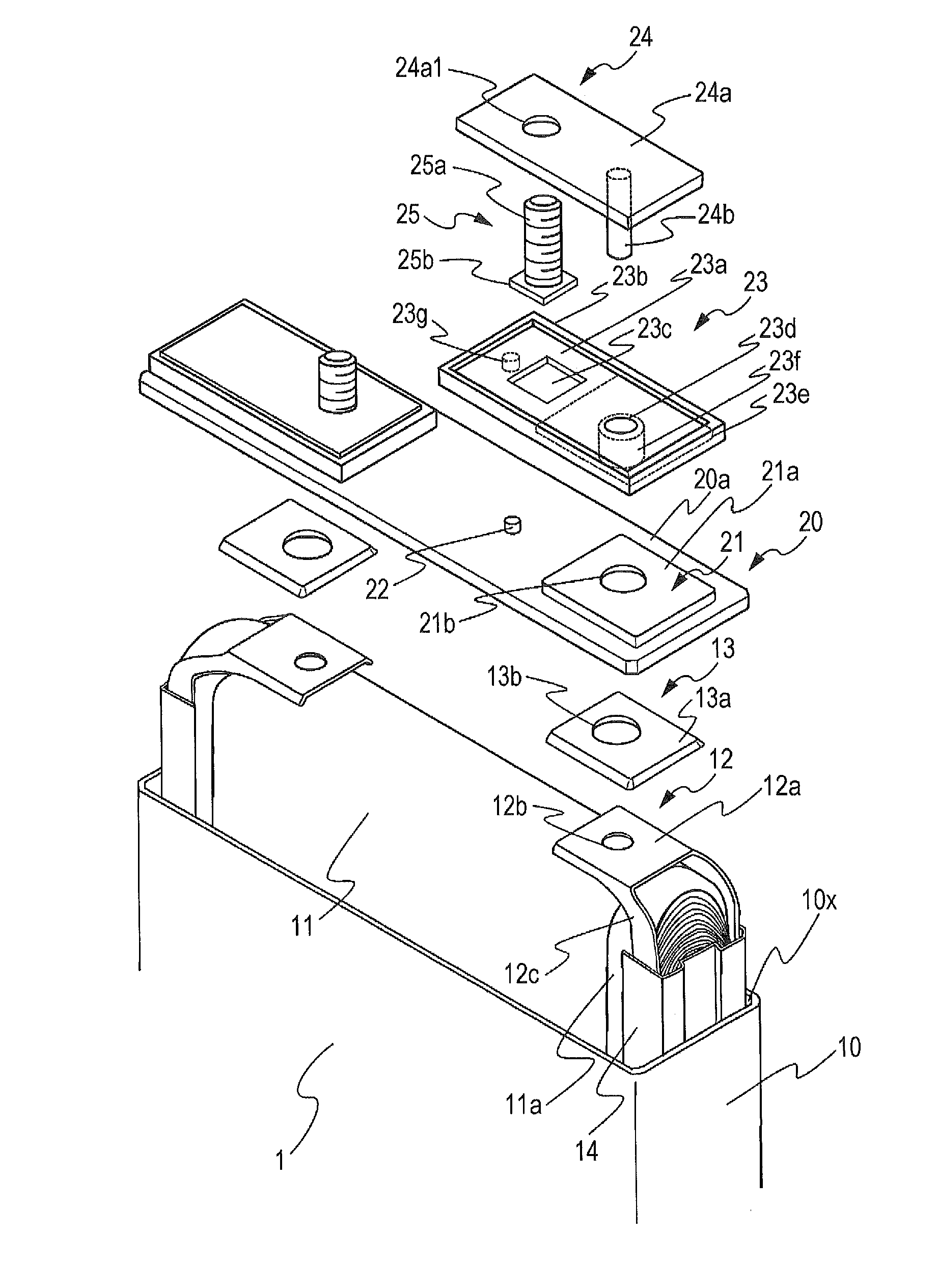
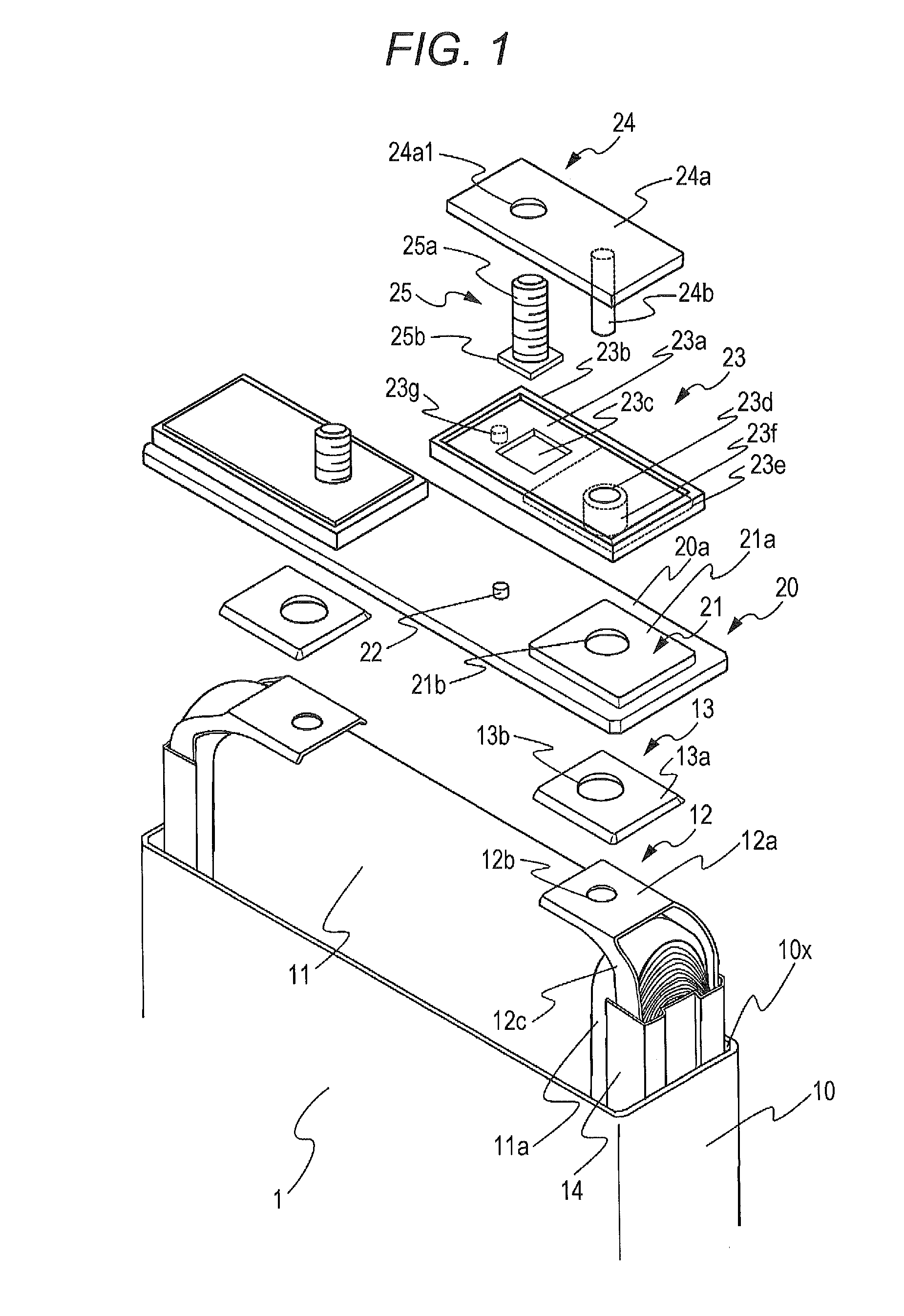
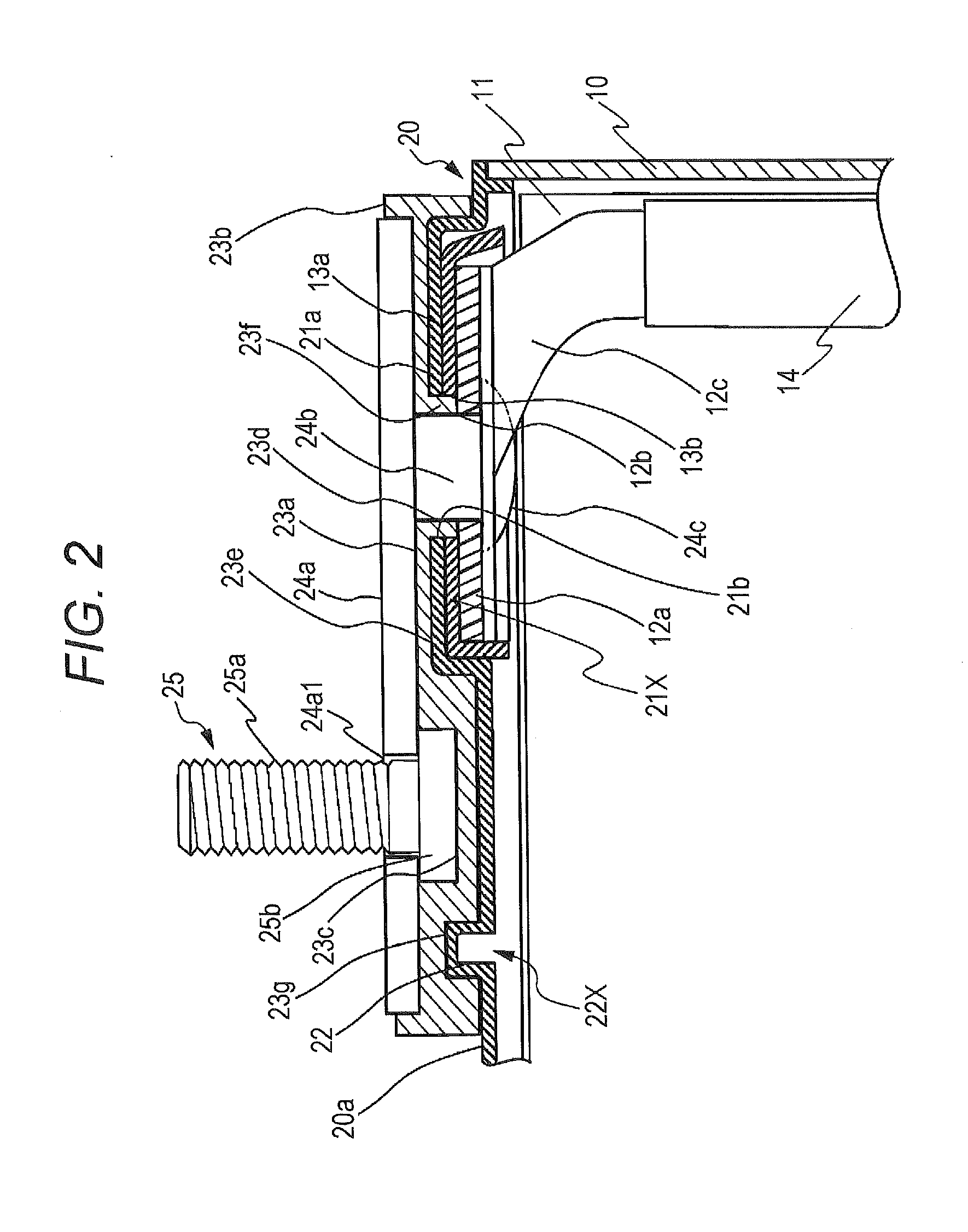
[0030]An electric storage device according to a first aspect of the present invention includes: a power generating element; a housing container that houses the power generating element; a connecting body electrically connected to the power generating element; and an insulating member that fits the housing container at a plurality of fitting portions, secures the connecting body, and insulates a conductive path, which includes the power generating element and the connecting body, and the housing container from each other.

[0031]According to a second aspect of the present invention, in the electric storage device according to the first aspect of the present invention, the connecting body includes a terminal member for external connecting, and respective positions of the plurality of fitting portions in the insulating member are different from a securing position of the terminal member in the insulating member.

[0032]According to a third aspect of the present invention, in the electric s...


PUM


Abstract

An electric storage device includes: a power generating element; a housing container that houses the power generating element; a connecting body electrically connected to the power generating element; and an insulating member that fits the housing container at a plurality of fitting portions, secures the connecting body, and insulates a conductive path, which includes the power generating element and the connecting body, and the housing container from each other.

Description

CROSS-REFERENCE TO RELATED APPLICATION[0001]This application is based on Japanese Patent Applications No. 2012-169017 filed with the Japan Patent Office on Jul. 30, 2012, the entire contents of which are hereby incorporated by reference.FIELD[0002]The present invention relates to an electric storage device and a power source module.BACKGROUND [0003]A secondary battery is used as a substitute for a primary battery. In addition, the secondary battery is in widespread use as a power source for an electronic device such as a mobile phone and an IT device. Especially, the nonaqueous electrolyte secondary cell typified by a lithium ion battery has a high energy density. Accordingly, application of the nonaqueous electrolyte secondary cell is being developed for a large industrial electrical machine such as an electric vehicle.[0004]FIG. 12 is an exploded perspective view illustrating a schematic configuration of a related nonaqueous electrolyte secondary cell. This type of nonaqueous elec...

Claims


Application Information

Patent Timeline
IPC IPC(8): H01M2/22H01M50/528H01M50/176
CPCH01M2/22H01M50/529H01M50/176H01M10/052H01M10/058Y02E60/10H01M50/528Y02P70/50H01M50/147H01M50/543
Inventor TONONISHI, MASAMITSUTSURUTA, SHOGONISHIKAWA, RYUTARO
Owner GS YUASA INT LTD
Why Eureka
Try Eureka