Mobile ballast device

a ballast device and mobile technology, applied in the direction of vessel safety, vessel movement reduction by mass displacement, floating buildings, etc., can solve the problems of increasing the weight of the canting keel, recurring damage sources, and not being well suited to boating in the port, so as to reduce the drag of the water, reduce the water drag, and improve the safety of the boa

a ballast device and mobile technology, applied in the direction of vessel safety, vessel movement reduction by mass displacement, floating buildings, etc., can solve the problems of increasing the weight of the canting keel, recurring damage sources, and not being well suited to boating in the port, so as to reduce the drag of the water, reduce the water drag, and improve the safety of the boa

US20140033961A1Inactive Publication Date: 2014-02-06DE TROZ VINCENT

Image

  • Mobile ballast device
  • Mobile ballast device
  • Mobile ballast device

Examples


Embodiment Construction

[0063]Throughout the following description, like numerals will denote like concepts and elements in different embodiments, so that for example the numerals 100, 200, 300, 400, 500, 600 each describe a different embodiment of the device according to the present invention.

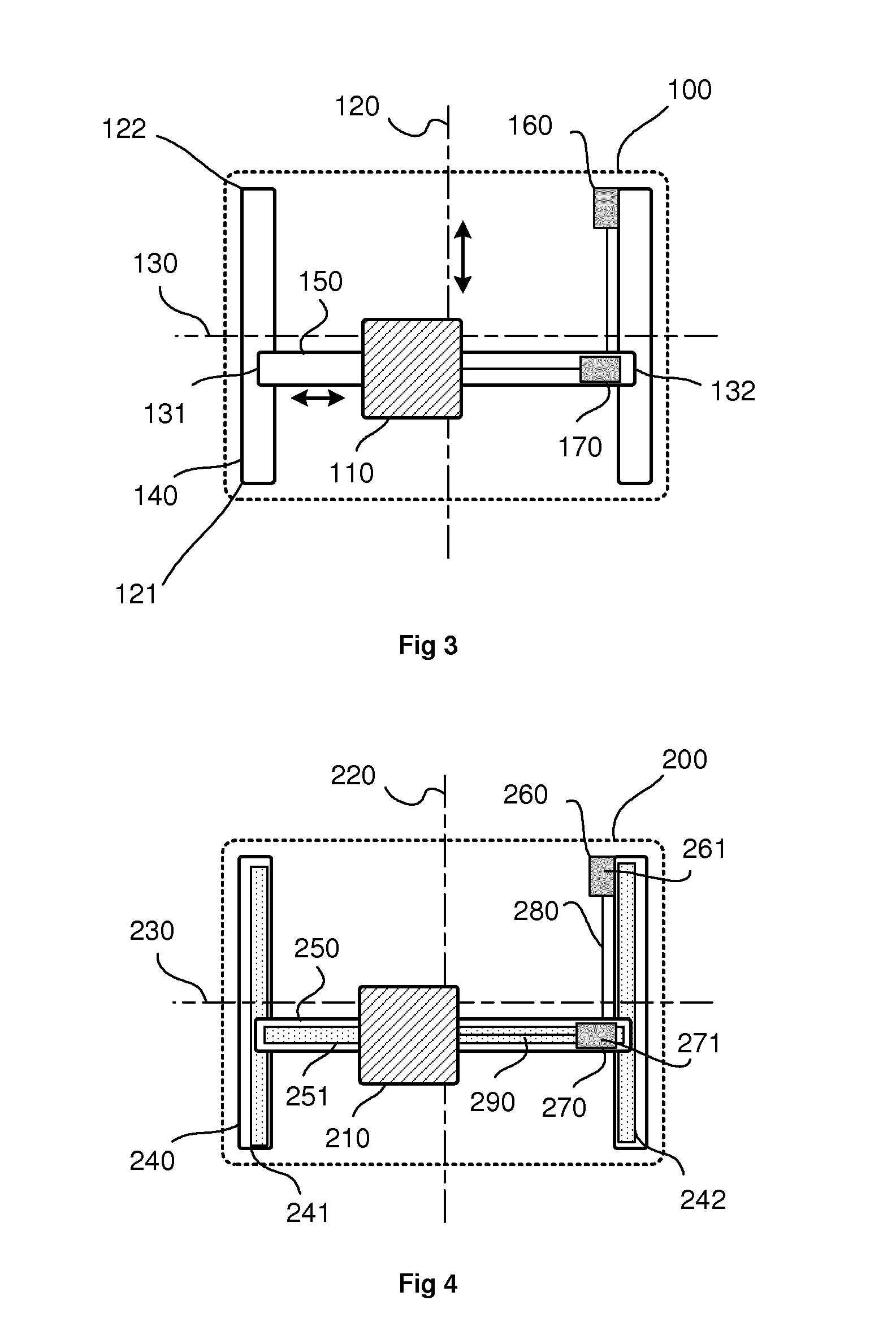
[0064]As shown in FIG. 3, the device 100 according to the present invention provides a ballast element 110, which is movable along two axes 120, 130 independently. A first axis 120 is defined by first ballast moving means 140, on which the ballast can take any position between a start 121 and end position 122. A second axis 130 is defined by second ballast moving means 150, on which the ballast element 110 can take any position between a start 131 and an end position 132. Preferably, the second moving means 150 are supported by the first moving means 140. The moving means 140, 150 are driven by first 160 and second operating means 170.

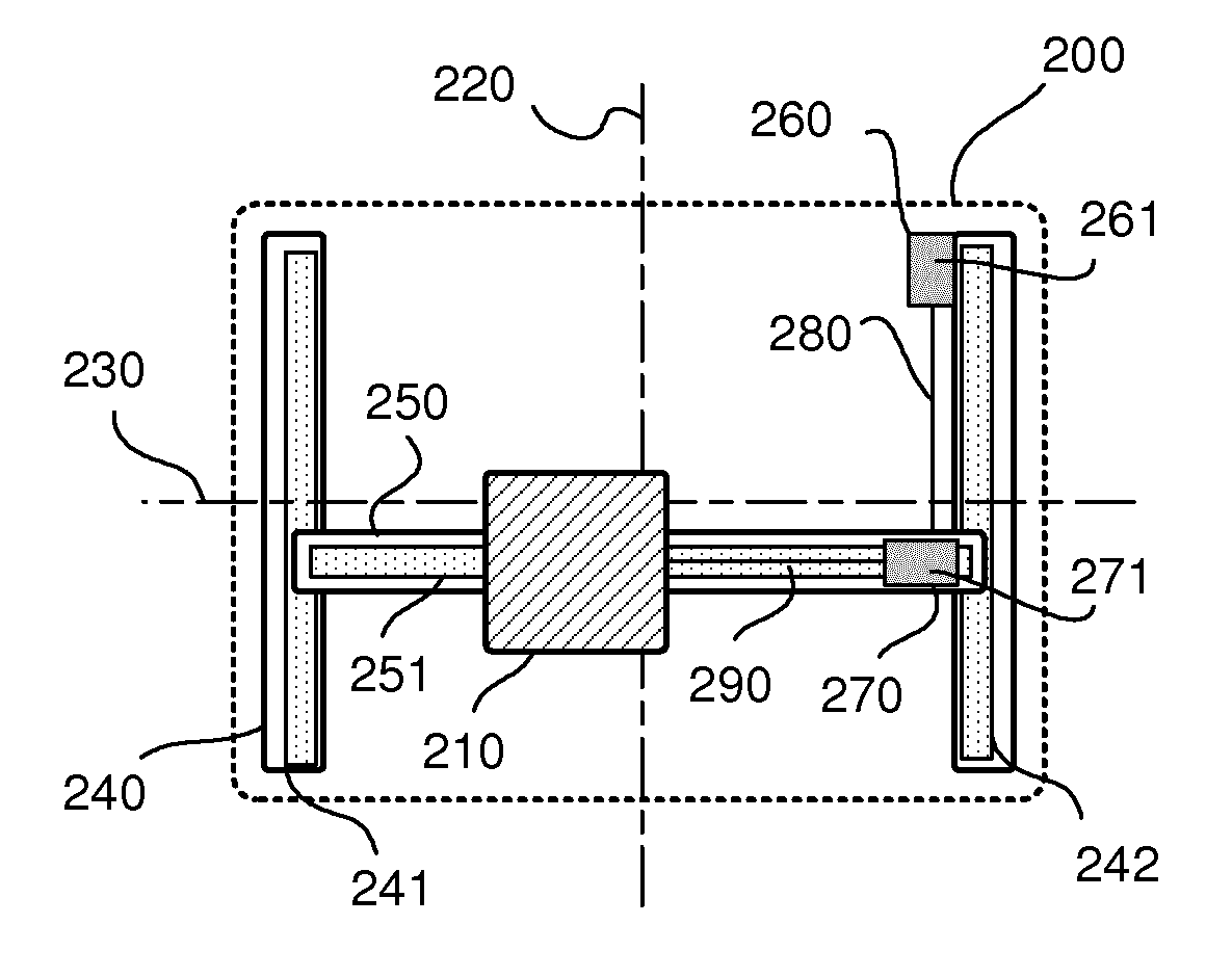
[0065]As shown in FIG. 4 and FIG. 5, the operating means 260, 270 may for example b...


PUM


Abstract

The present invention discloses an inside mobile ballast arrangement for sailboats, said arrangement using a dense material and being preferably in a watertight / gas-tight compartment, the whole system on low friction bearings and being close to the bottom of the hull, this arrangement being able to move longitudinally from front to rear and vice versa, along the X axis, independently or simultaneously with a perpendicular displacement, i.e. from port to starboard and vice versa, along the Y axis.

Description

TECHNICAL FIELD[0001]The present invention relates to mobile ballast devices for boats, and in particular to mobile ballast devices for monohull sailboats.BACKGROUND OF THE INVENTION[0002]In order to ensure stability while sailing, a sailboat requires a system to counterbalance the thrust of the wind in the sails. For convenience, we shall denote a first longitudinal axis of a sailboat, running from bow to stern, as the X-axis. A second, transverse axis, running sideways from port to starboard will be called the Y-axis.OVERVIEW OF THE THEORY[0003]As illustrated in FIG. 1a, the centre of buoyancy B is the centre of gravity of the volume of water 003 that is displaced by the hull 001. When a hull is subjected to no wind force, the hull's centre of gravity G and the centre of buoyancy B are on a same line, which is substantially perpendicular to the body of water 002.[0004]As illustrated in FIG. 1b, a sailboat begins to tilt, or heel in the Y-axis, as soon as the wind presses into the ...

Claims


Application Information

Patent Timeline
06 Feb 2014
Publication
US20140033961A1
IPC
B63B39/02
CPC
B63B39/02; B63B43/08
Inventors
DE TROZ, VINCENT