Dynamic backup ring assembly

a technology of dynamic backing ring and ring assembly, which is applied in the field of mechanical equipment, can solve the problems of destroying the dynamic backing seal, scoring and galling the shaft sealing surface, and damage to the housing and the shaft sealing surface, and achieves the effect of minimizing pressure-induced extrusion damag

Active Publication Date: 2014-02-06
KALSI ENG
View PDF10 Cites 14 Cited by
  • Summary
  • Abstract
  • Description
  • Claims
  • Application Information

AI Technical Summary

Benefits of technology

[0027]The present invention relates generally to dynamic seals used for establishing sealing between relatively movable machine components for separation of first and second fluids, and for retention of the first fluid, even when the pressure of the first fluid is considerably greater than the pressure of the second fluid. More specifically, the preferred embodiment is a mechanical arrangement that applies the pressures of the first and second fluids to controlled locations on a backup ring in order to provide substantial pressure balance in the radial direction, and if desired, substantially balanced force in the axial direction. The radial pressure balance makes the backup ring relatively immune to pressure-induced dimensional changes. The axial force balance frees the backup ring to align itself on the shaft and to follow lateral deflection and runout of the shaft. These benefits allow the backup ring to define a small initial extrusion gap for the dynamic seal, minimizing pressure-induced extrusion damage to the dynamic seal.
[0037]The pressure of the second fluid is preferably communicated to the outer periphery of the backup ring so that the pressure of the second fluid acts on both the inner and outer peripheries of the backup ring. The pressure of the second fluid can be communicated to the outer periphery of the backup ring by any suitable means, such as one or more holes / pressure ports penetrating from the inner periphery of the backup ring to the outer periphery of the backup ring, or such as one or more holes / pressure ports passing through the housing structure that locates the backup ring. Both of these described pressure communication methods can be incorporated at the same time, if desired. If desired, the inner periphery of the backup ring can incorporate a circular groove for rapid circumferential distribution of the pressure of the second fluid into the clearance between the backup ring and the shaft, and can include an axial slot for rapid communication of the pressure of the second fluid to the circular groove.
[0041]If desired, the higher pressure of the first fluid can be used to create a radially outwardly acting hydraulic force to counteract the radial force imbalance resulting from the greater area of the outer periphery as compared to the inner periphery of the backup ring. For example, the axial spacing between the first and second outer sealing sites can be made a little greater than the axial spacing between the first and second inner sealing sites and the difference in axial spacing can be acted upon by the first fluid pressure. This allows the first fluid pressure to create a radially outwardly acting hydraulic force to compensate for radial force imbalance resulting from the greater area of the outer periphery as compared to the inner periphery of the backup ring.
[0047]The backup ring preferably has a modulus of elasticity at the annular gap that is greater than the modulus of elasticity of the resilient sealing material of the dynamic seal. The backup ring faces and bridges the annular gap between the housing and the relatively movable member, and defines and minimizes the effective extrusion gap clearance that the dynamic seal is exposed to, which increases the differential pressure capability of the dynamic seal. Metals and some plastics are examples of backup ring materials that have a modulus of elasticity that is greater than the modulus of elasticity of resilient seal materials. The preferred material for construction of the majority of the backup ring is metal, and preferably is a high modulus metal such as steel.

Problems solved by technology

The resulting friction and heat can destroy the dynamic seal, and may damage the housing and the shaft sealing surface in ways that are highly detrimental to the effective life of the dynamic seal.
Heavily loaded shaft-to-housing contact can also occur with reciprocating shafts due to misalignment related binding, and can lead to scoring and galling of the shaft sealing surface.
Pressure causes seal material to protrude into extrusion gap clearance.
The damage cycle continues until sealing function is lost.
Manufacturing tolerances are large, which directly affects the size of the shaft-to-housing clearance, and also increases bearing mounting and internal clearances, which all permit shaft run-out and misalignment.
Large components are often subject to significant elastic deformation when exposed to high pressure and large mechanical loads.
Surface speeds can be significant in large diameter rotary equipment, which adds to seal-generated heat.
This softens the seal material, and reduces seal extrusion resistance.
However, there is much potential for misalignment between the lower shaft and the seal housing.
This large piston is necessarily mounted with enough clearance for sliding, which adds to its potential for misalignment.
The piston is a two-piece assembly, which also adds to the potential for misalignment of the sealing surface.
The drillstring is in all likelihood misaligned with the rotating control device, and not running true.
This imposes severe cocking loads on the reciprocating piston, causing misalignment and run-out that can cause heavily loaded contact at the extrusion gap that is likely to damage the dynamic seal, the shaft, and the seal housing.
As a general conclusion concerning large equipment such as rotary control devices, if clearance is in a useful range for extrusion resistance, it is virtually impossible to guide the shaft so precisely that it will not rub on the bore of a conventional non-floating seal housing.
This rubbing creates seal-damaging heat, and may also damage the seal housing and shaft in ways that significantly accelerate rotary seal extrusion damage.
The differential pressure that such dynamic seals can retain is limited by the extrusion resistance of the material used in the construction of the seal, and is also limited by the size of the extrusion gap clearance that exists between the seal housing and the mating relatively movable surface.
The backup rings used with static and reciprocating seals are unsuitable for rotary seals exposed to high differential pressure due to liabilities such as high friction, high wear, material flow, and damaging frictional heat.
The seal carriers of these patents require a step change in shaft diameter, and therefore cannot accommodate the significant shaft reciprocation found in some types of rotary equipment, such as the rotating control devices shown in U.S. Pat. Nos. 5,588,491 and 5,662,171.
Another problem with the seal carriers of U.S. Pat. Nos. 5,195,754 and 6,227,547 is that seals and seal carriers of different diameters are typically required for pressure staging.
This deflection has to be taken into account when designing the journal bearing fit, the extrusion gap fit, and the axial fit of the seal carrier with the surrounding support structure.” The problem with merely taking the deflection into account when designing the extrusion gap fit is that the extrusion gap closes as differential pressure builds, trapping extruded sealing material.

Method used


Image

  • Dynamic backup ring assembly
  • Dynamic backup ring assembly
  • Dynamic backup ring assembly

Examples


Embodiment Construction

[0064]The aspects, features, and advantages of the embodiments of the invention mentioned above are described in more detail by reference to the drawings, wherein like reference numerals represent like elements.

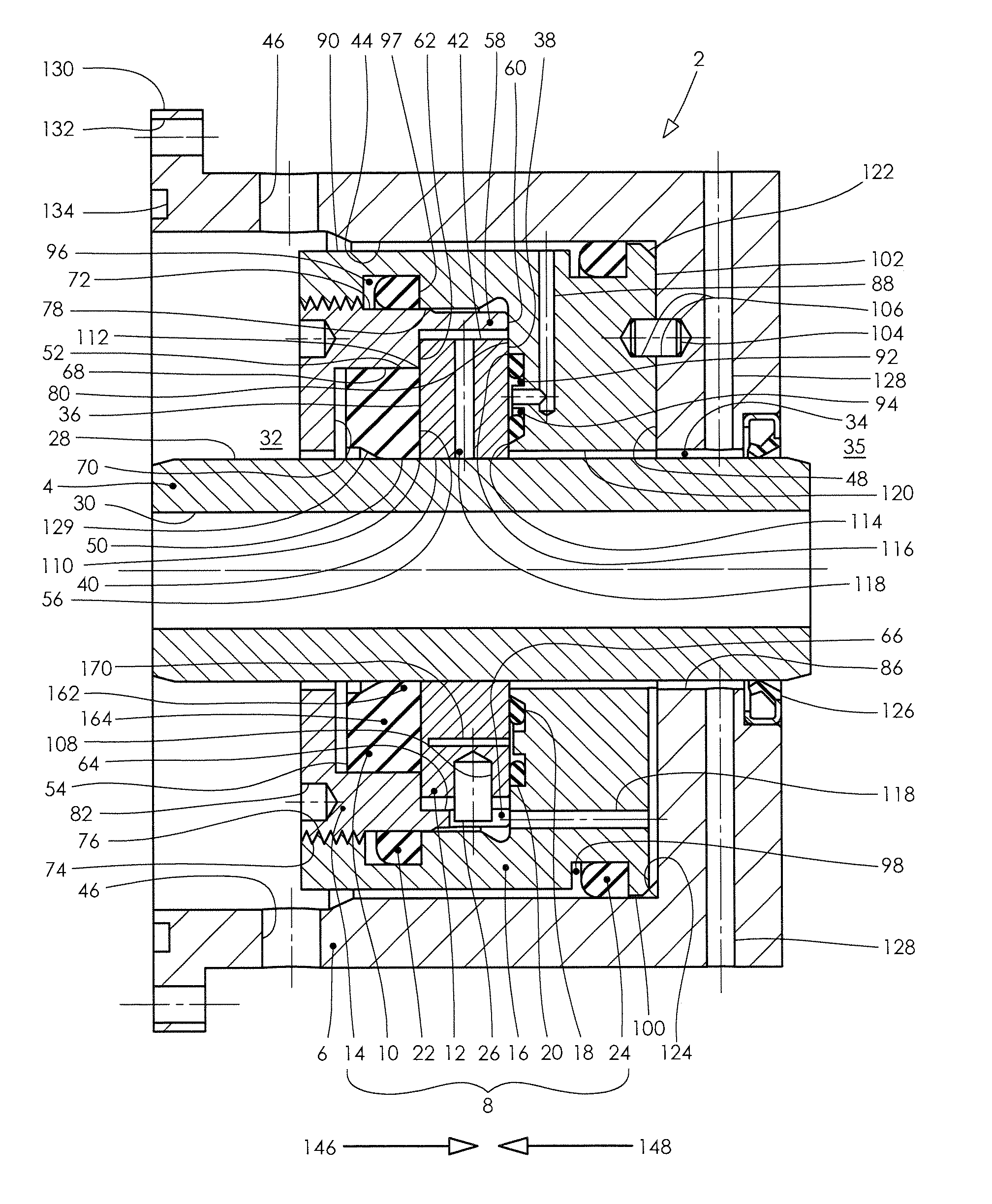
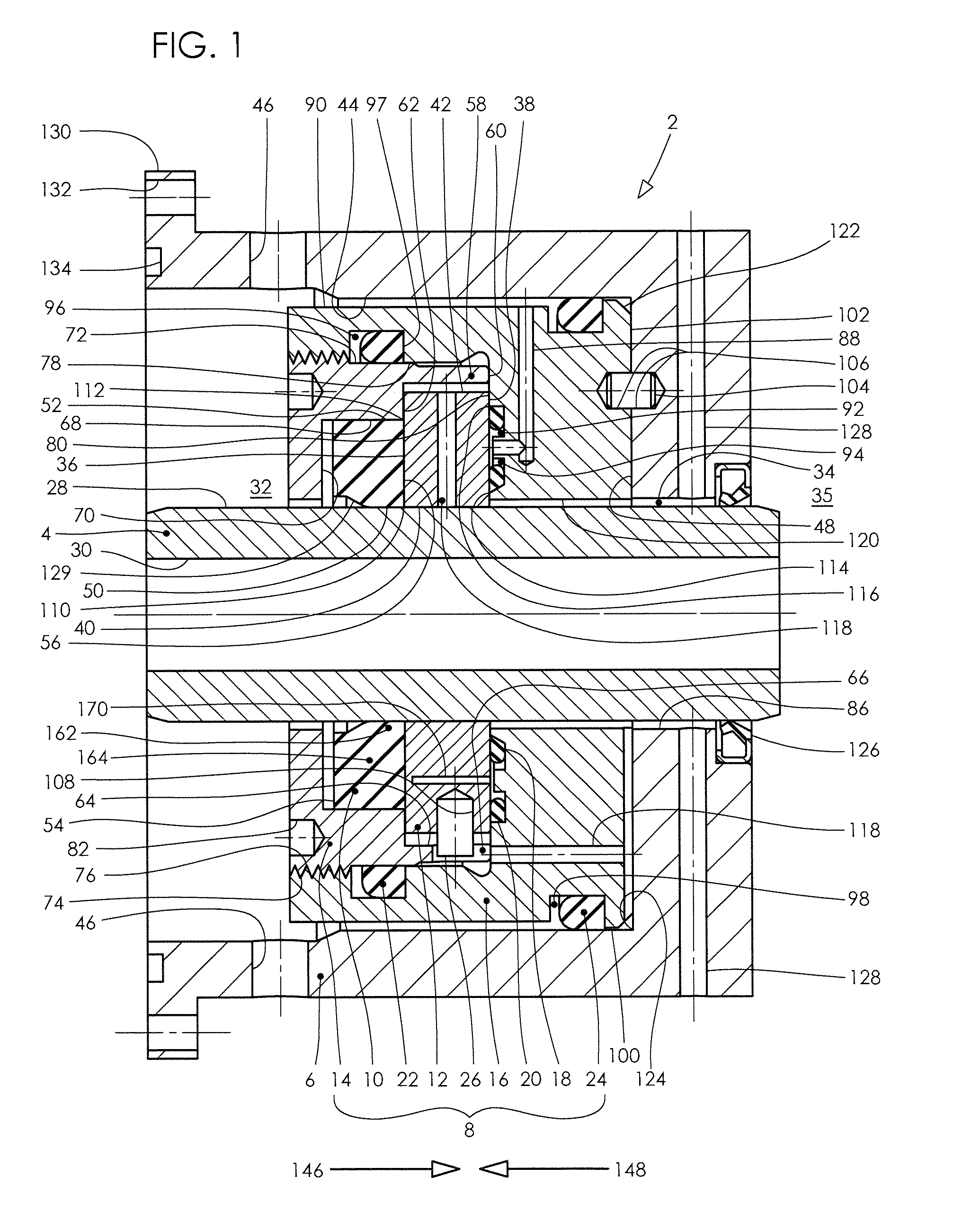
[0065]FIG. 1 features throughout this specification that are represented by like numbers have the same basic function. Referring now to the drawings and first to FIG. 1, a longitudinal cross-sectional view of a sealed machine assembly is shown generally at 2, showing the parts located concentrically to one another.

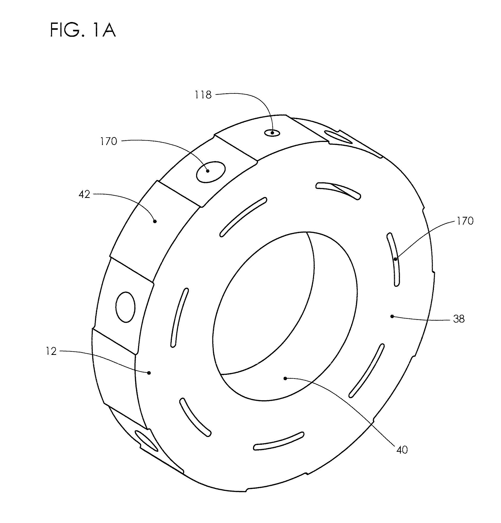
[0066]The machine assembly 2 incorporates a shaft 4 that is relatively movable with respect to a machine housing 6, and is relatively movable with respect to a sealing assembly 8. The sealing assembly 8 is preferably comprised of a number of components including a dynamic seal 10, a backup ring 12, a retainer 14, a bulkhead housing 16, an inner balancing seal 18, an outer balancing seal 20, a retainer seal 22, a housing seal 24, and an anti-rotation tang 26.

[0067]By...


PUM


Abstract

A seal backup ring assembly is provided that eliminates fluid differential pressure acting radially on the backup ring, preventing collapse of the backup ring against a shaft. The backup ring is assembled so that the initial clearance (extrusion gap) between the backup ring and relatively rotating member is not affected by the differential pressure acting across the assembly. This allows for an initially small extrusion gap to be present throughout the differential pressure range.

Description

CROSS-REFERENCE TO RELATED APPLICATIONS[0001]This application is a continuation-in-part application of U.S. application Ser. No. 12 / 957,160, filed Nov. 30, 2010, entitled “Pressure-Balanced Floating Seal Housing Assembly and Method” which claims the benefit of U.S. Provisional Application Ser. No. 61 / 283,227 filed Nov. 30, 2009, entitled “Seal Carrier,” and claims the benefit of U.S. Provisional Application Ser. No. 61 / 284,179 filed Dec. 14, 2009, entitled “Pressure-Balanced Floating Seal Carrier,” and is a continuation-in-part application of U.S. application Ser. No. 13 / 026,045, filed Feb. 11, 2011, entitled “Hydrodynamic Backup Ring” which claims the benefit of U.S. Provisional Application Ser. No. 61 / 337,667 filed Feb. 11, 2010 and entitled “High Pressure Rotary Seal.” This application claims the benefit of U.S. Provisional Application Ser. No. 61 / 795,217 filed Oct. 12, 2012, entitled “Force Balanced Backup Ring for Sealing Assembly,” and claims the benefit of U.S. Provisional Ap...

Claims


Application Information

Patent Timeline
Patent Type & Authority Applications(United States)
IPC IPC(8): F16J15/44
CPCF16J15/441F16J15/006F16J15/166
Inventor RICHIE, AARON PAULDIETLE, LANNIE LAROY
Owner KALSI ENG
Why Eureka
Try Eureka