Vibration actuator

Active Publication Date: 2014-02-06
NIDEC COPAL CORPORATION
View PDF22 Cites 48 Cited by
  • Summary
  • Abstract
  • Description
  • Claims
  • Application Information

AI Technical Summary

Benefits of technology

[0016]According to present invention, it is possible to prevent ab

Problems solved by technology

In addition, when the first compression coil spring rubs against or collides with the inner-side enlarged portion,

Method used


Image

  • Vibration actuator
  • Vibration actuator
  • Vibration actuator

Examples


Example

[0029]Preferred embodiments of a vibration actuator according to the present invention are hereunder described in detail with reference to the drawings.

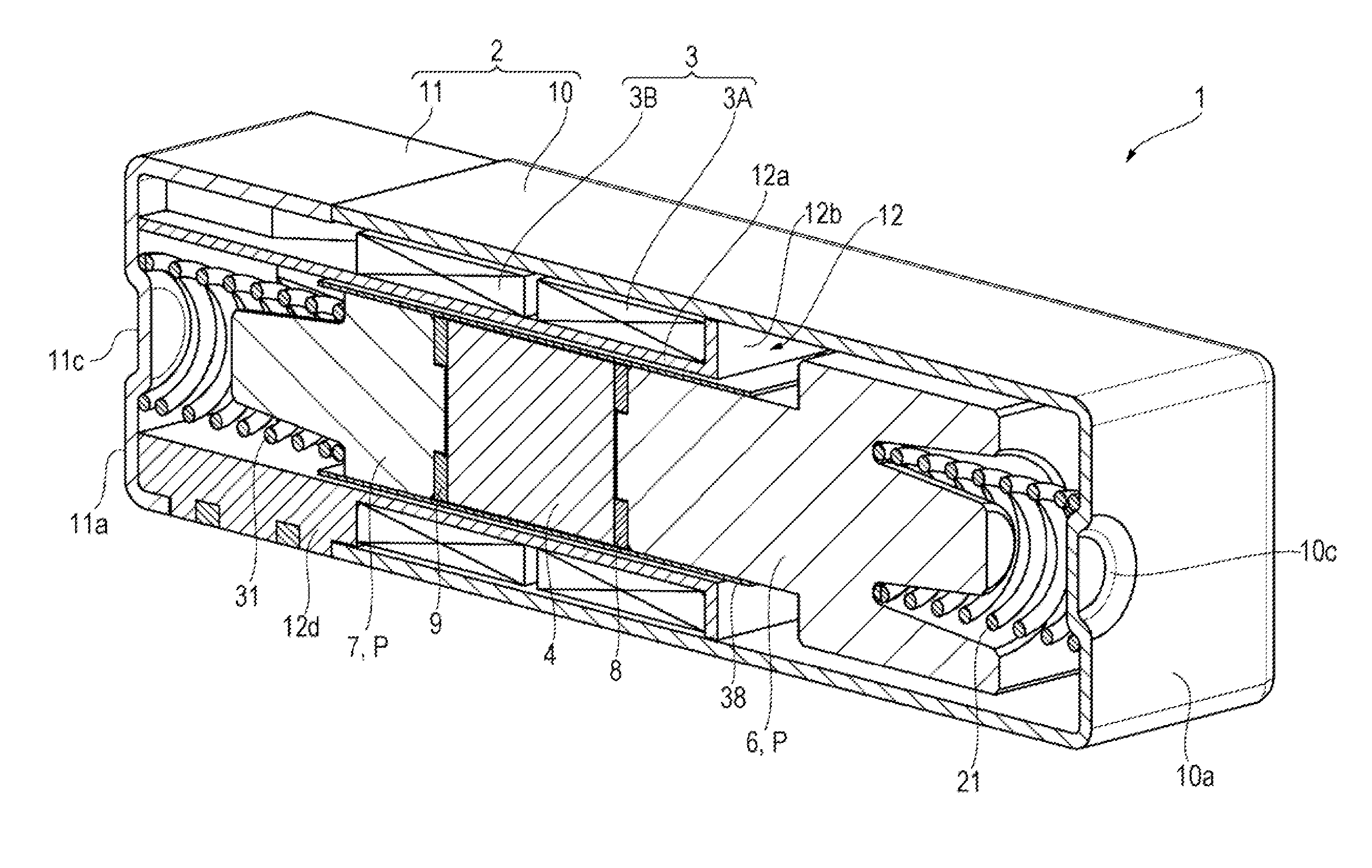
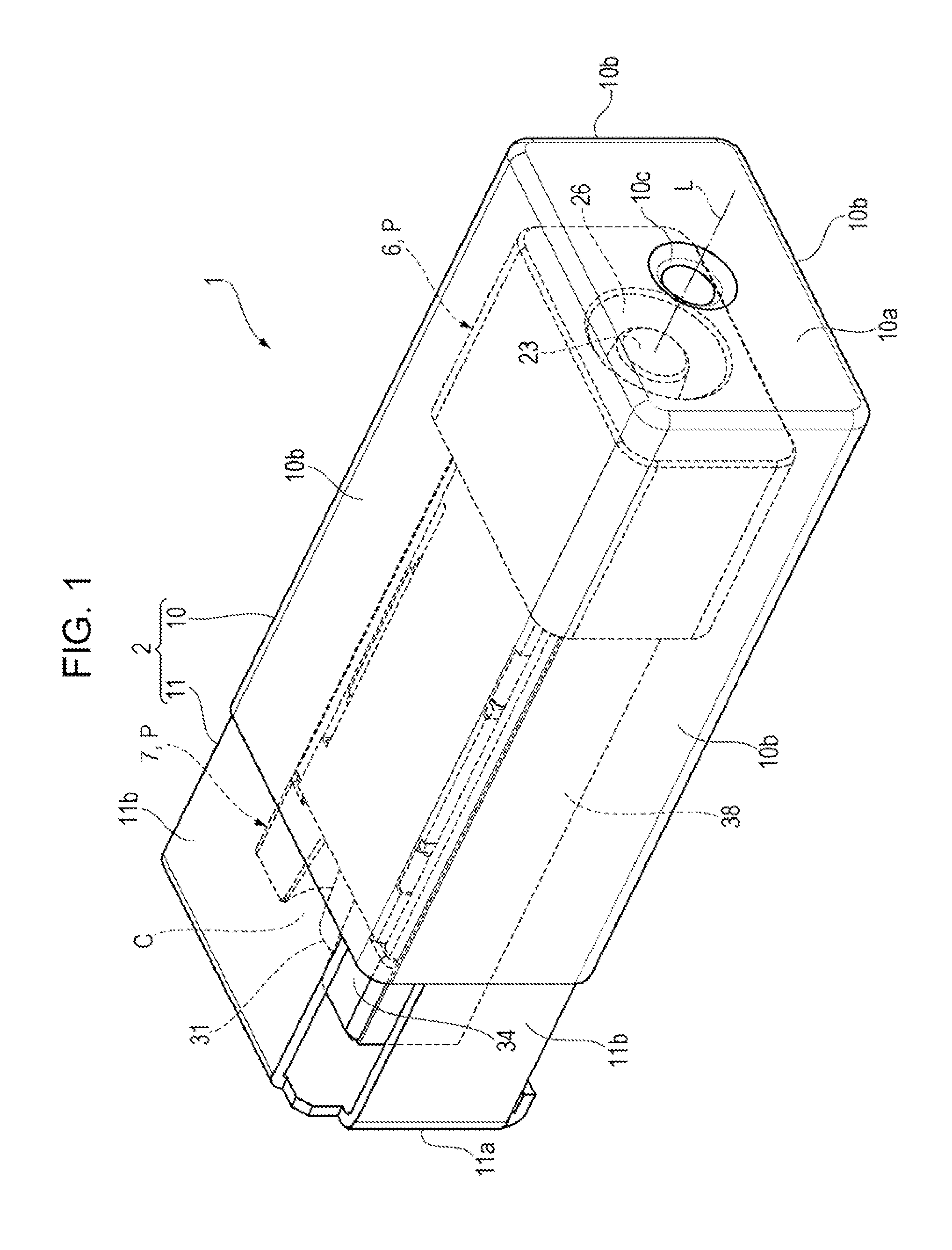
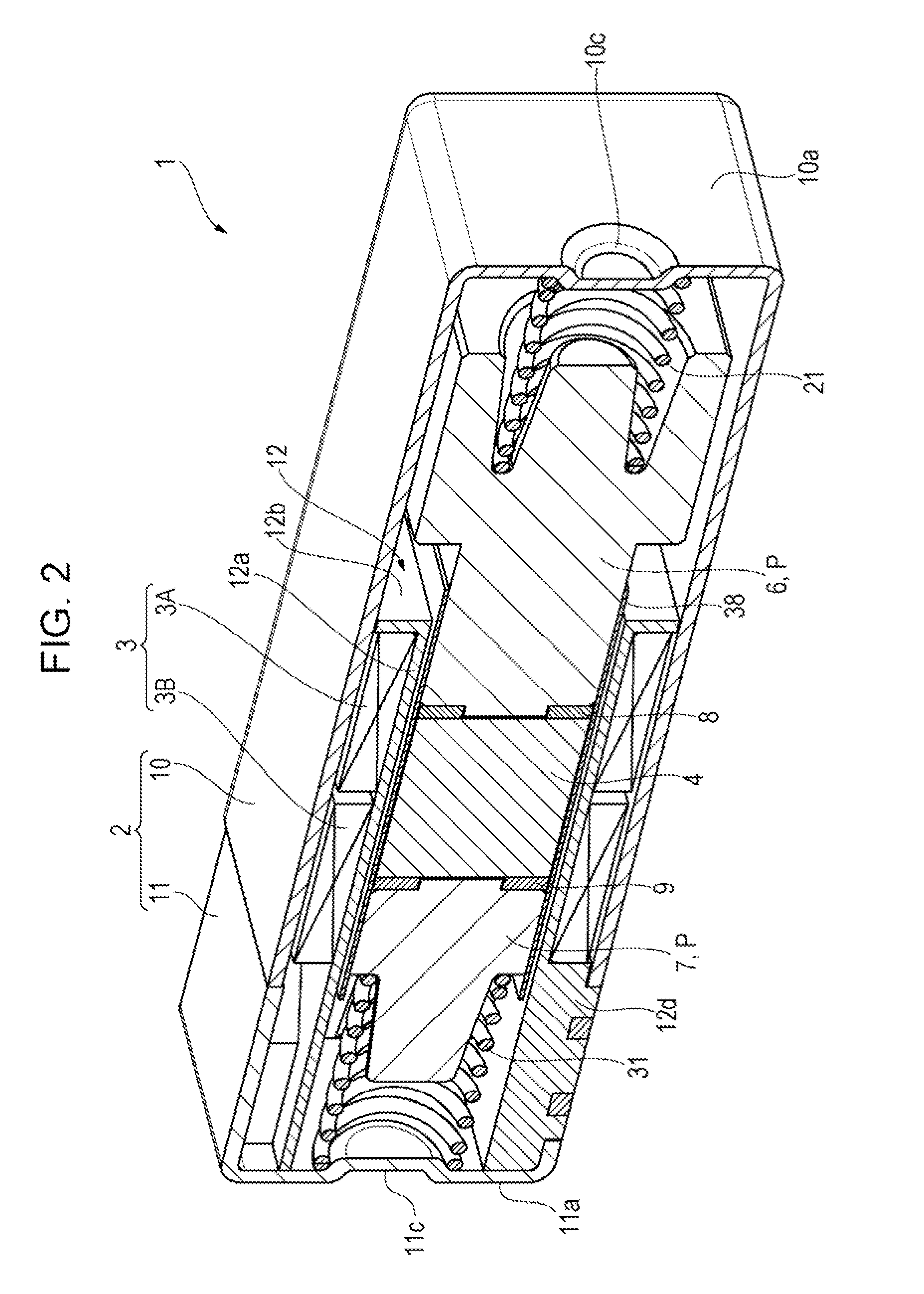
[0030]As shown in FIGS. 1 to 3, a small vibration actuator 1 includes a parallelepiped housing 2 that has a height of 4 mm, a width of 6 mm, and a length of 15 mm and that is hollow. A coil 3, a parallelepiped magnet 4, a first weight portion 6, a second weight portion 7, a first pole piece 8, and a second pole piece 9 are accommodated in the housing 2 formed of a magnetic material. The coil 3 is formed by being wound around a vibration axis L of the housing 2 into a rectangular shape in cross section. The magnet 4 is surrounded by the coil 3. The first weight portion 6 and the second weight portion 7 are disposed adjacent to corresponding sides of the magnet 4 in a direction of the vibration axis L of the housing 2. The first pole piece 8 and the second pole piece 9 are affixed to corresponding end surfaces of the magnet 4, are annu...


PUM


Abstract

A first weight portion of a vibration actuator includes an inner-side enlarged portion that protrudes from an end portion of a solid head in a direction of a vibration axis and that is inserted into an opening portion extending within a first compression coil spring along the direction of the vibration axis. An outer peripheral surface of the inner-side enlarged portion becomes continuously smaller in diameter from a base end towards a free end, with the vibration axis being the center of the diameter. That is, the inner-side enlarged portion has the shape of a truncated cone. The inner-side enlarged portion is inserted into the opening portion of the first compression coil spring and the opening portion is utilized to change the length of the inner-side enlarged portion in the direction of the vibration axis, thereby changing the mass of the first weight portion.

Description

CROSS REFERENCES TO RELATED APPLICATIONS[0001]The present invention contains subject matter related to Japanese Patent Application No. 2012-170333 filed in the Japan Patent Office on Jul. 31, 2012, the entire contents of which are incorporated herein by reference.BACKGROUND OF THE INVENTION[0002]1. Field of the Invention[0003]The present invention relates to a small vibration actuator used in, for example, a vibration generating source for notifying a user of an incoming call of a portable wireless device such as a cellular phone, or a vibration generating source for providing tactile sensation of a touch panel of a portable wireless device or reality of a game played by a game device to a user's finger or hand.[0004]2. Description of the Related Art[0005]Hitherto, as a technology in such a field, the technology described in Japanese Unexamined Patent Application Publication No. 2003-220363 (PTL 1) is provided. The vibration actuator described in PTL 1 includes a cup-shaped yoke in ...

Claims


Application Information

Patent Timeline
IPC IPC(8): H02K33/18
CPCH02K33/18H02K33/16
Inventor ENDO, MASAYATONOGAI, YOSHIHIDE
Owner NIDEC COPAL CORPORATION
Why Eureka
Try Eureka