Method for the production of a flame ionization detector and corresponding flame ionization detector

Inactive Publication Date: 2014-02-06
KROHNE MESSTECHNICK GMBH & CO KG
6 Cites 4 Cited by

AI-Extracted Technical Summary

Problems solved by technology

Based on the fact that substrates that consist of different materials are used with temperature coefficients that are different to some extent, the detector can be adversely affe...

Benefits of technology

[0013]The object of the invention is a method for the production of a μFID, which avoids the drawbacks of the prior art and results in a μFID, which...

Abstract

A flame ionization detector having at least one combustion chamber, at least one conduit for directing a gas or gas mixture, and at least one electrode structure, and a process for forming the flame ionization detector by providing two or more green ceramic films, forming geometric structures in said green ceramic films, depositing at least a portion of an electrically conductive structure on at least one of said green ceramic films, stacking said green ceramic films, laminating said green ceramic films, and sintering said laminated green ceramic films to faun said flame ionization detector.

Application Domain

Technology Topic

Flame ionization detectorElectrically conductive +5

Image

  • Method for the production of a flame ionization detector and corresponding flame ionization detector
  • Method for the production of a flame ionization detector and corresponding flame ionization detector
  • Method for the production of a flame ionization detector and corresponding flame ionization detector

Examples

  • Experimental program(1)

Example

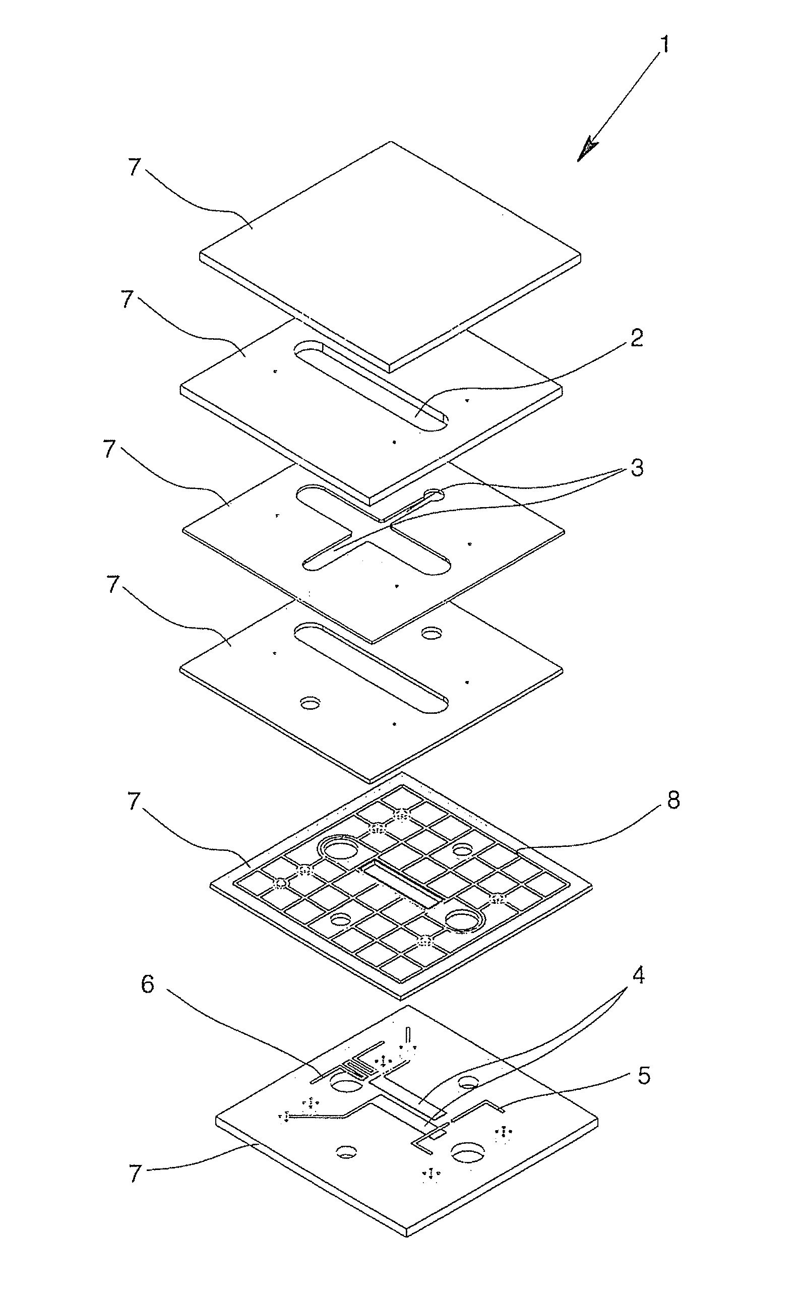
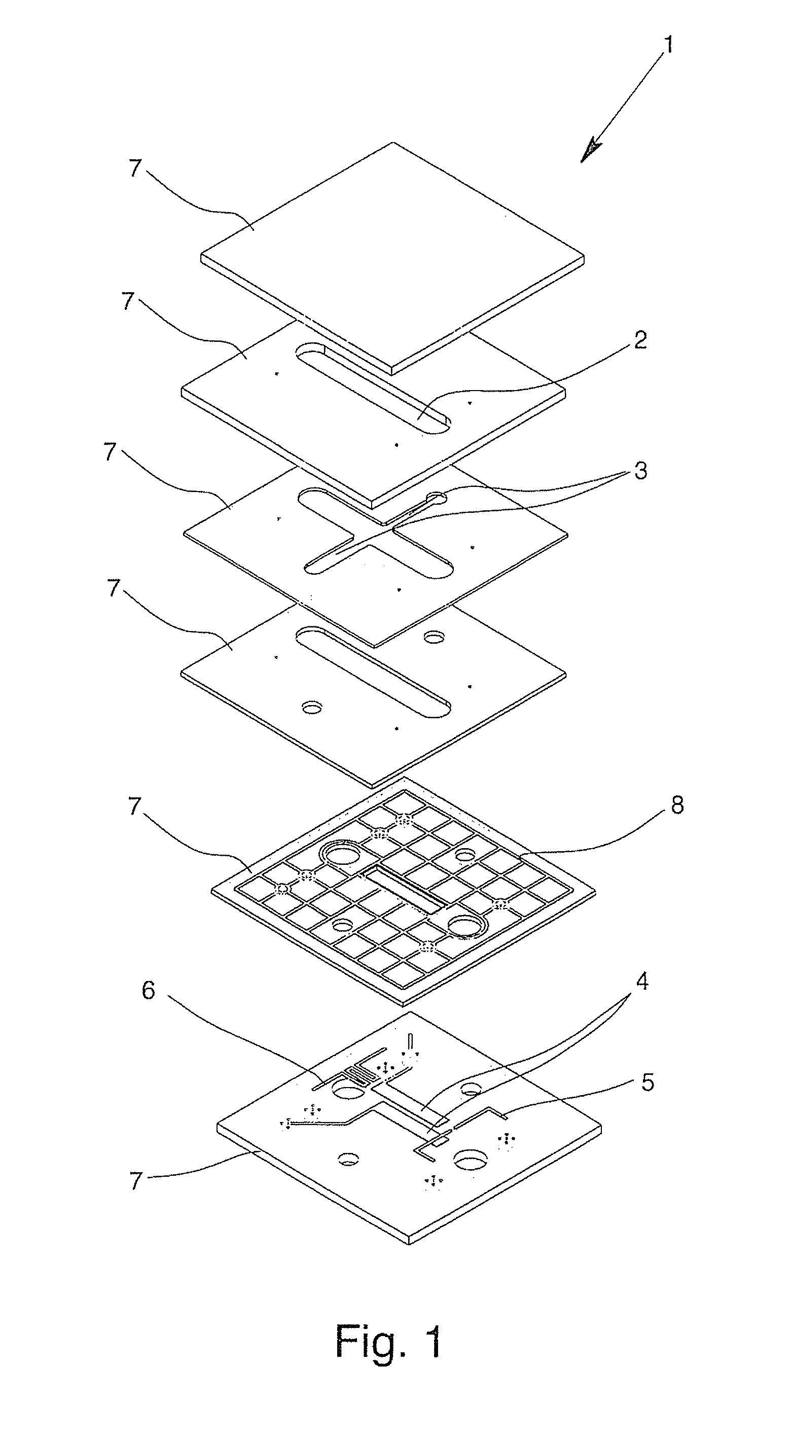
[0028]In an exploded view, FIG. 1 shows a flame ionization detector 1 that has six planes or six blocks and that is configured in particular as a μFID. The combustion chamber 2, in which the sample to be examined is ionized in a hydrogen flame, is located centrally. Channels 3 are used to supply combustion gas or oxidizing agent and then also to drain off the combustion gas, and said channels empty via so-called nozzles into the combustion chamber 2.
[0029]The ion stream is measured by the electrode structure 4 as part of the electrically conductive or in particular metal structure with a measuring electrode and a counter-electrode and in particular preferably also a protective electrode 8 by an electrical voltage being applied to the measuring electrode and the counter-electrode. The measured stream allows an assessment of the concentration of a certain substance in the medium that is to be examined.
[0030]For production of the flame, an ignition device 5 is also provided. In addition, the measurement uses a temperature sensor 6, which is shown here in the form of a meandering temperature-dependent resistor.
[0031]The flame ionization detector 1 consists of several blocks of single or multiple ceramic films 7, which in each case have a structure in the form of through-recesses or cavities, which when stacked are combined as a whole to form the hollow spaces that are necessary for the operation of the flame ionization detector 1. In addition, the necessary electrical structures, such as the electrode structure 4, the conductor structures that are necessary, for example, for directing the measurement signals, or else an essentially mesh-like protective electrode 8 are also provided on the ceramic films 7 or the blocks that are formed therefrom in each case. The electrically conductive structures preferably run inside the flame ionization detector 1 and provide through contacts for the connections, here directed downward in the figures. Preferably, all other supply conduits or discharge conduits for gases, liquids, electrical connections, thermal connections or lead-aways are also directed to one side or to one surface, here in particular to the bottom of the flame ionization detector 1. This allows the flame ionization detector 1 to be used, for example, as an SMD component and to be mounted directly on other structures.
[0032]As parts of the electrode structure 4, ignition device 5, temperature sensor 6, etc., the individual electrically conductive or metal structures, connections, through-recesses, measuring electrodes and counter-electrodes are depicted here all bundled above the bottommost block of the ceramic films 7 for clarity of depiction. In the depiction, this results in the mesh-like protective electrode 8 being arranged above the electrode structure 4 with measuring electrodes and counter-electrodes. For practical implementation, however, the protective electrode 8 can be located in a plane between the measuring electrode and the counter-electrode.
[0033]In one configuration (not depicted here) the counter-electrode, the temperature sensor 6 and/or the ignition device 5 are located below the topmost block, which is designed to be planar and without geometric structures. In this case the topmost block operates as a cover. On this cover, additional (not depicted here) components can optionally also be mounted, thus, e.g., a cooling unit.
[0034]FIG. 2 shows a section through a pure diagrammatic arrangement of a configuration of the electrode structure 4 that is an alternative to FIG. 1. Shown primarily is the area of the protective electrode 9 that is designed as an alternative for a mesh-like protective electrode 8 of FIG. 1. A protective electrode 9, which is separated electrically from the measuring electrode 11 by an insulator 10 (e.g. a dielectric paste), is located on a ceramic film 7. Above the measuring electrode 11, there is another insulator 10 and consequently another protective electrode 9. The measuring electrode 11 is therefore completely surrounded by the protective electrode 9. For insulation, for example, a dielectric paste can also be applied, preferably even when turned on the sides.
[0035]FIG. 3 indicates a sequence of the individual steps of the method according to the invention.
[0036]In Step 100, individual green ceramic films or blocks 7 are arranged in groups or stacks. In Step 101, structures are generated in groups, e.g., by punching, milling or etching. Thus, the geometries that when combined as a whole form conduits for gases or for through-recesses, etc., in the finished flame ionization detector are introduced.
[0037]In Step 102, the electrical or in particular metal structures, elements, etc., are applied on the ceramic films. This, for example, can be at least partially accomplished by a silk-screening method.
[0038]In Step 103, the involved ceramic films/blocks are stacked, and in Step 104, they are laminated, in order to be subjected to a sintering process in Step 105.
[0039]In Step 106, a machine-finishing of the sintered ceramic monolith also takes place.
[0040]While the present invention has been described and illustrated by reference to particular embodiments, those of ordinary skill in the art will appreciate that the invention lends itself to variations not necessarily illustrated herein. For this reason, then, reference should be made solely to the appended claims for purposes of determining the true scope of the present invention.

PUM

PropertyMeasurementUnit
Temperature1000.0°C
Temperature1600.0°C
Temperature1800.0°C
tensileMPa
Particle sizePa
strength10

Description & Claims & Application Information

We can also present the details of the Description, Claims and Application information to help users get a comprehensive understanding of the technical details of the patent, such as background art, summary of invention, brief description of drawings, description of embodiments, and other original content. On the other hand, users can also determine the specific scope of protection of the technology through the list of claims; as well as understand the changes in the life cycle of the technology with the presentation of the patent timeline. Login to view more.

Similar technology patents

Classification and recommendation of technical efficacy words

Why Eureka
Try Eureka