Working range diagram and working range diagram-display apparatus

Inactive Publication Date: 2014-02-06
TADANO LTD
View PDF12 Cites 5 Cited by
  • Summary
  • Abstract
  • Description
  • Claims
  • Application Information

AI Technical Summary

Benefits of technology

[0014]According to the first feature of the present invention, the working range can be easily grasped because the working range is shown three-dimensionally. Therefore, a mistake in a work plan is hardly made due to a subjective impression or a misunderstanding, thereby preventing rework or the like.
[0015]According to the second feature of the present invention, the working range can be more easily grasped because the frontward performance, the backward performance, the right sideward performance and the left sideward performance can be distinguished from each other.
[0016]According to the third feature of the present invention, the working range can be easily grasped because the working range is shown three-dimensionally. Therefore, a mistake in the work plan is hardly made due to a subjective impression or a misunderstanding, thereby preventing rework or th

Problems solved by technology

Therefore, it is difficult for a worker unfamiliar with the working range diagram to imagine a three-dimensional working range.
Unf

Method used


Image

  • Working range diagram and working range diagram-display apparatus
  • Working range diagram and working range diagram-display apparatus
  • Working range diagram and working range diagram-display apparatus

Examples


Embodiment Construction

[0028]An embodiment of the present invention will now be described with reference to the drawings.

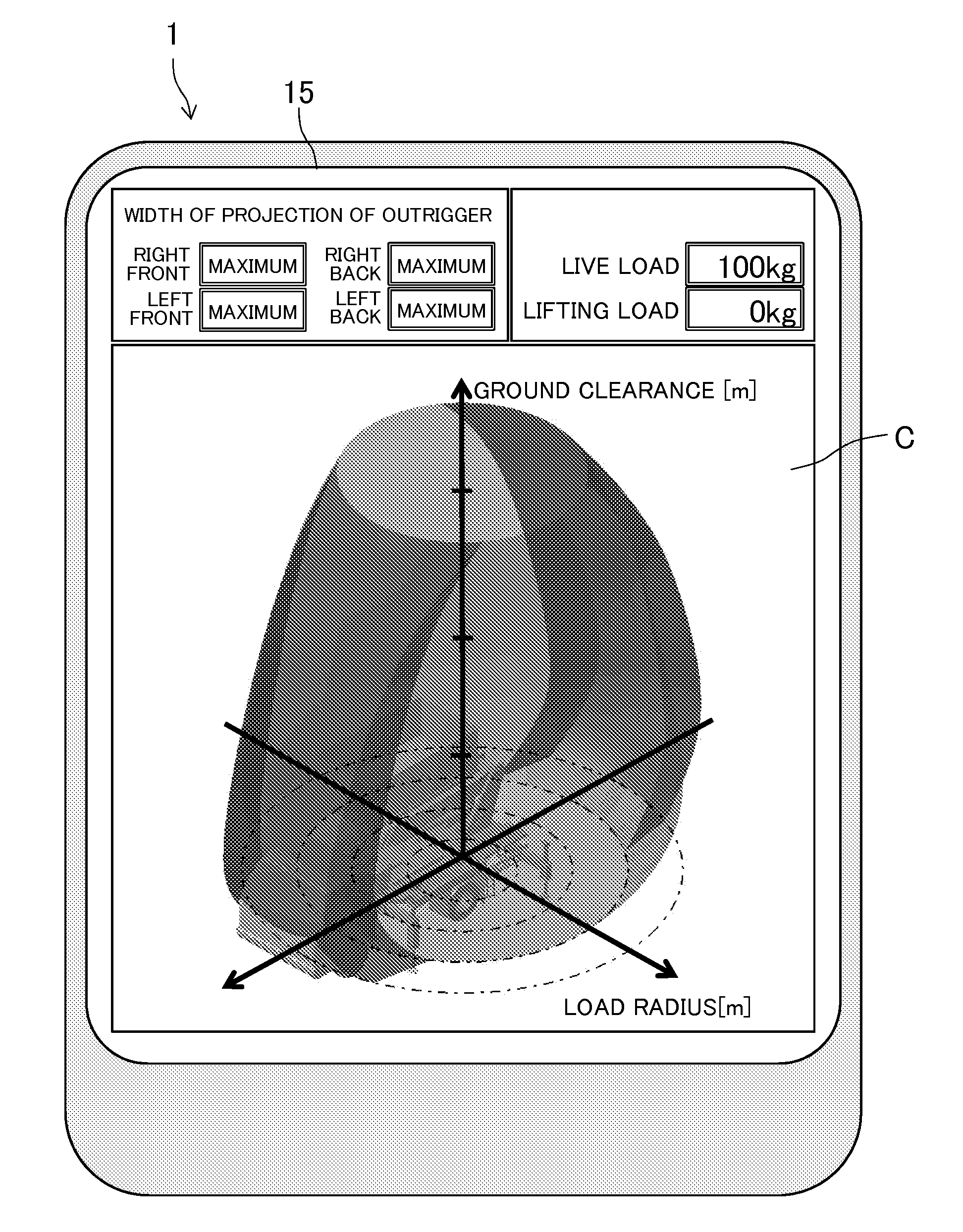
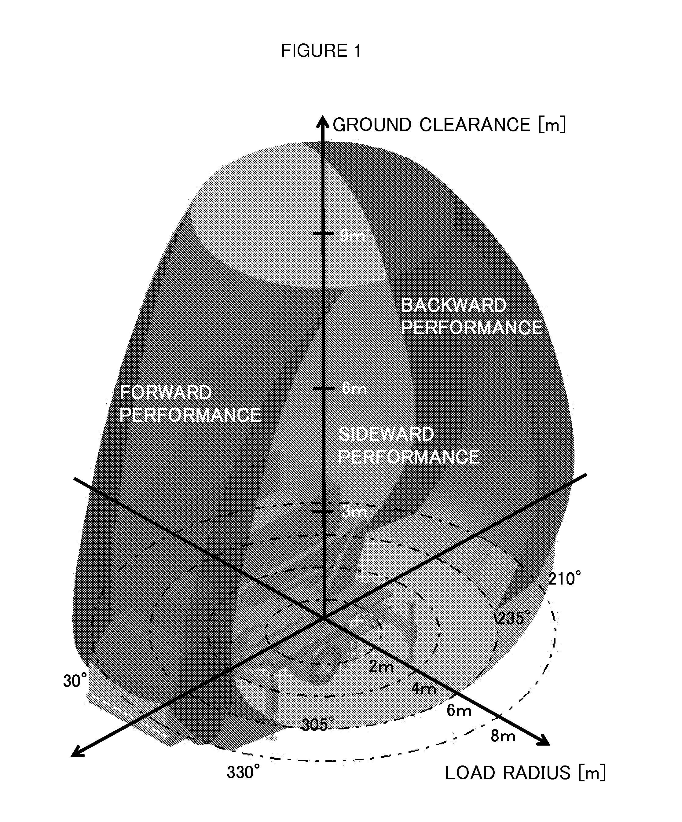
[0029]A working range diagram according to the present invention shows a working range for working machines having a boom such as boom lifts or cranes. Although a boom lift will be described as an example hereinafter, the working range diagram of the present invention can be similarly applied to the other working machines.

[0030]A configuration of a common boom lift 100 is first described with reference to FIG. 9. In FIG. 9, reference numeral 110 indicates a vehicle, which is provided with outriggers 111 ensuring stability during working in addition to a driving source for vehicle running, an operator cab and wheels. Four outriggers 111 are provided at four corners on all sides of a platform of the vehicle 110 in the shown example. A swivel base 120 is mounted on a rear side of the platform of the vehicle 110. A hydraulic motor or the like allows the swivel base 120 to swivel 360 degrees...


PUM


Abstract

Provided is a working range diagram and a working range diagram-display apparatus with which a working range can be easily grasped. The working range diagram shows a working range in which a boom of a working machine having the boom can safely move with a three-dimensional spatial coordinate system. In the working range diagram, a part of or all of forward performance, backward performance, right sideward performance and left sideward performance in the working range is shown in different display formats. Since the working range is shown three-dimensionally and the frontward performance, the backward performance, the right sideward performance and the left sideward performance can be distinguished from each other, the working range can be easily grasped. Consequently, a mistake in a work plan is hardly made due to a subjective impression or a misunderstanding, thereby preventing rework or the like.

Description

[0001]Priority is claimed on Japanese Patent Application 2012-170702, filed Aug. 1, 2012.BACKGROUND OF THE INVENTION[0002]1. Field of the Invention[0003]The present invention relates to a working range diagram and a working range diagram-display apparatus and, more particularly, to a working range diagram and a working range diagram-display apparatus for a working machine having a boom such as a boom lift.[0004]2. Description of the Related Art[0005]As for working machines having a boom such as boom lifts, a range where safe working is ensured is defined in a movable region of the boom in terms of stability against overturning or strength of a component. A working range diagram is used for showing such a working range, and thereby a work plan is made based on the working range diagram.[0006]A conventional working range diagram is shown with a two-dimensional spatial coordinate system with a horizontal axis indicating a load radius and a vertical axis indicating a ground clearance. A...

Claims


Application Information

Patent Timeline
IPC IPC(8): G06T11/60
CPCG06T11/60B66C23/905
Inventor OSHIMA, MASANORIKUMANO, KAORI
Owner TADANO LTD
Why Eureka
Try Eureka