
Optical information recording medium, recording and reproduction method, and recording and reproduction device

a technology of optical information and recording medium, which is applied in the direction of data recording, instruments, track shape, etc., can solve the problems of adverse effects, modulation of the amplitude of the recorded signal as the track width fluctuates, and the method of forming the address information on the disc, etc., to achieve high reliability, suppress the influence of wobble interference, and the effect of sufficient resistan

Active Publication Date: 2014-02-06
HITACHI CONSUMER ELECTRONICS CORP +1
View PDF6 Cites 2 Cited by
  • Summary
  • Abstract
  • Description
  • Claims
  • Application Information

AI Technical Summary

Benefits of technology

The invention provides a method and device for reliable and high-speed recording and playback of optical information. It solves the problem of wobble interference and is capable of overcoming disc faults such as defective wobble configuration and ADIP errors caused by dust and dirt. This makes it easier to build an ADIP system that is highly reliable and less affected by errors.

Problems solved by technology

When a recordable-type optical disc system using the land-groove method is constructed, a method of forming the address information on the disc is one of the fundamental problems to be solved.
That is, since the width of the groove or the land changes in such a section, an adverse effect is observed that the amplitude of the recorded signal is modulated as the track width fluctuates.
Moreover, in the pertinent section, an adverse effect that the amplitude of the wobble signal also fluctuates is received at the same time.
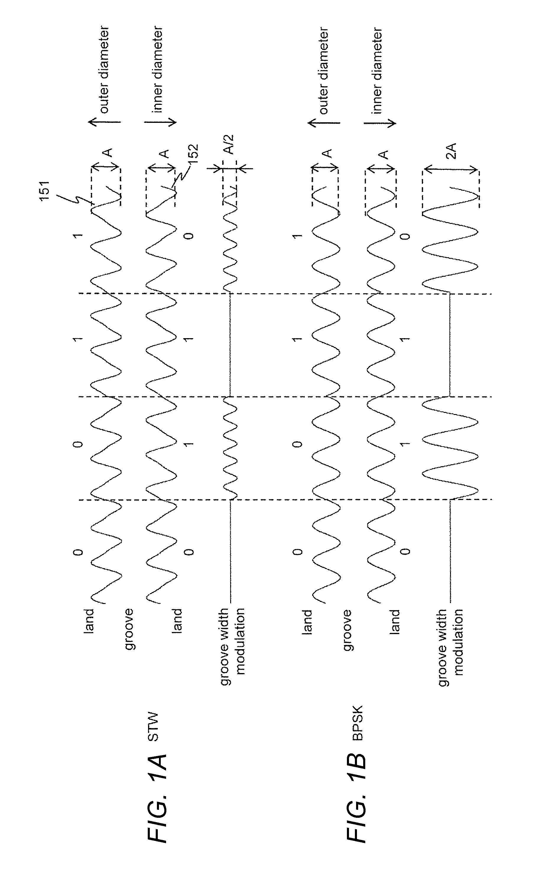
However, since BPSK (binary phase shift keying) is used as the wobble modulation means, there is a problem in that a high wobble interference occurs in a part where the configurations of the side walls of the adjoining grooves are not the same as each other.
Moreover, according to the technique described in Patent Document 1, it is not performed to protect the ADIP by an error correction code (ECC).
The technique described in Patent Document 1 has a problem in that the reliability of the ADIP information reproduced from the wobble signal is low since the ADIP is not protected by the error correction code.
In particular, it has a problem of being extremely vulnerable to an ADIP error due to a disc fault such as a defective wobble configuration and an ADIP error due to dust and dirt adhering to the disc surface.

Method used


Image

  • Optical information recording medium, recording and reproduction method, and recording and reproduction device
  • Optical information recording medium, recording and reproduction method, and recording and reproduction device
  • Optical information recording medium, recording and reproduction method, and recording and reproduction device

Examples


Embodiment Construction

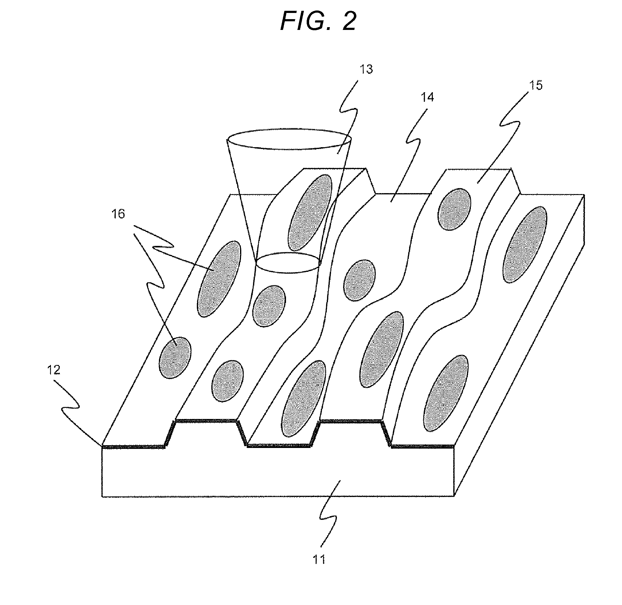
[0037]First, the land-groove method will be described again. FIG. 2 is a view explaining the arrangement of recording marks 16 according to the land-groove method. On a disc substrate 11, a flat-bottom groove, that is, a groove 14 as shown in FIG. 2 is formed. The groove is formed of a uniform pitch spiral. As mentioned previously, the groove is wobbled. The substrate surface divided by the uniform pitch spiral groove will be referred to as a land 15. While the land and the groove are defined in various manners, in this specification, an area that is concave when viewed from the light incident surface is defined as the groove, and an area that is convex is defined as the land. On the land and the groove, a recording layer 12 is formed, and recording and reproduction of the recording marks 16 are performed by an optical spot 13. Since a recording mark stream is formed along each of the land and the groove, they will also be referred to as a land track and a groove track so as to indi...


PUM


Abstract

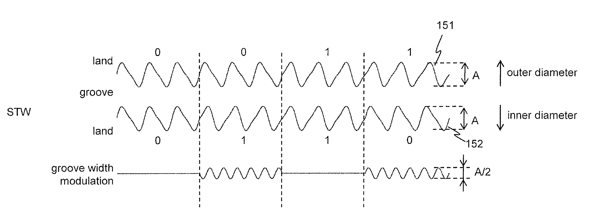
In the land-groove method, wobble interference is reduced. STW modulation is used as wobble modulation for a part where wobble interference can occur, for example, a part where the configurations of both side walls of the groove are not the same and groove width modulation is unavoidable. Thereby, the amplitude of the groove width modulation can be suppressed to a quarter of that when BPSK modulation is used.

Description

BACKGROUND OF THE INVENTION[0001]1. Field of the Invention[0002]The present invention relates to a medium on which information is recorded by using light and an information recording and reproduction device using the same.[0003]2. Description of the Related Art[0004]Some of the terms used in the following are expressions used for Blu-ray Disc (BD). These might be called by different terms for systems other than BD. However, one of ordinary skill in the art can easily read the terms as the different ones.[0005]The enlargement of the recording capacity of optical discs has been realized by increasing the number of recording layers per disc as well as by shortening the wavelength of the light source and increasing the numerical aperture (NA) of the objective lens. For BD, using a blue semiconductor laser and a high NA objective lens with an NA of 0.85, a recording capacity of 50 GB has been realized with two layers. Further, in 2010, by increasing the number of recording layers to thre...

Claims


Application Information

Patent Timeline
IPC IPC(8): G11B7/007
CPCG11B7/00718G11B7/24082G11B2007/00754
Inventor KIKUGAWA, ATSUSHI
Owner HITACHI CONSUMER ELECTRONICS CORP
Learn More