Electrical connectivity within architectural glazing frame systems

a technology of electrical connectivity and glazing frame, applied in the direction of instruments, door/window protective devices, optics, etc., can solve the problems of wire routing systems that are believed to be expensive and potentially error-prone, and wire routing systems that often require customization

Active Publication Date: 2014-02-13
SAGE ELECTROCHROMICS
View PDF1 Cites 45 Cited by
  • Summary
  • Abstract
  • Description
  • Claims
  • Application Information

AI Technical Summary

Problems solved by technology

Such wire routing systems are believed to be expensive and potentially error prone, often requiring the use of not only a technician for installing the IGUs, but also electricians for the wire routing and potentially structural engineers due to the modifications made to the framing system.
Furthermore, these wire routing systems often require customization due to the variety of commercial and residential framing systems in use today.

Method used


Image

  • Electrical connectivity within architectural glazing frame systems
  • Electrical connectivity within architectural glazing frame systems
  • Electrical connectivity within architectural glazing frame systems

Examples


Embodiment Construction

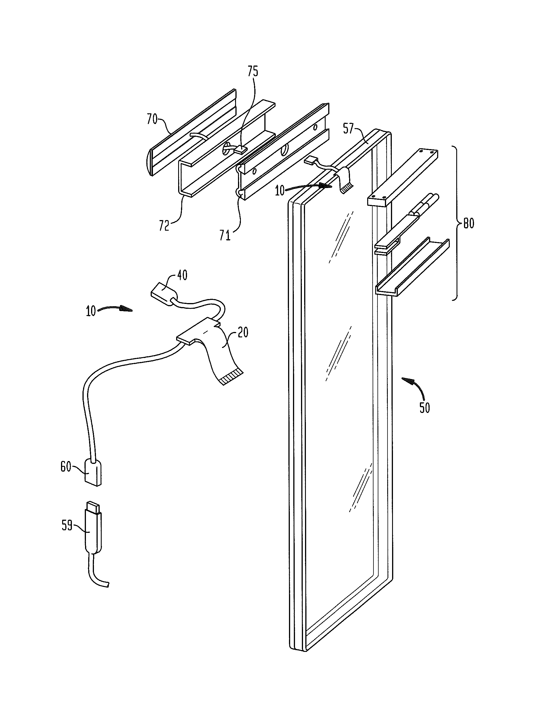
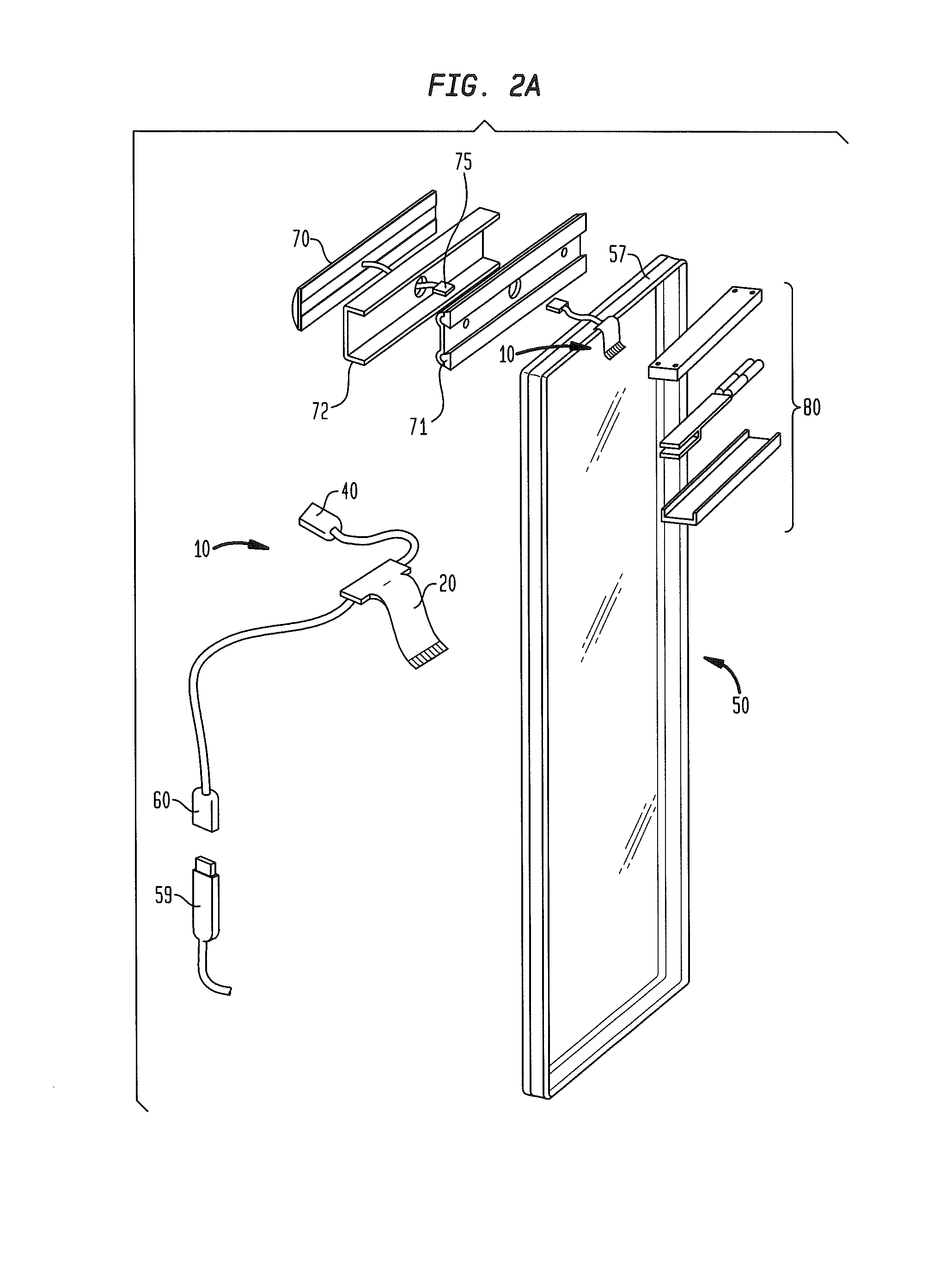
[0051]Referring to FIGS. 2A-2C, in accordance with one embodiment of the present invention, a connectivity harness 10 may be connected to the IGU 50 along a portion thereof. As shown, the connectivity harness 10 has a central connectivity module 11 for routing electrical signals between a conduit cable 20, a panel connector 40, and an IGU connector 60. The connectivity module 11 may be placed at a portion of an insulator 57. The insulator may be made of a dielectric material including, but not limited to, silicone and is provided or applied such that it surrounds the perimeter of the IGU 50. The conduit cable 20 may extend from the connectivity module 11 around the inner glass lite 12 and between the inner seal 2 and the inner glass lite 12.

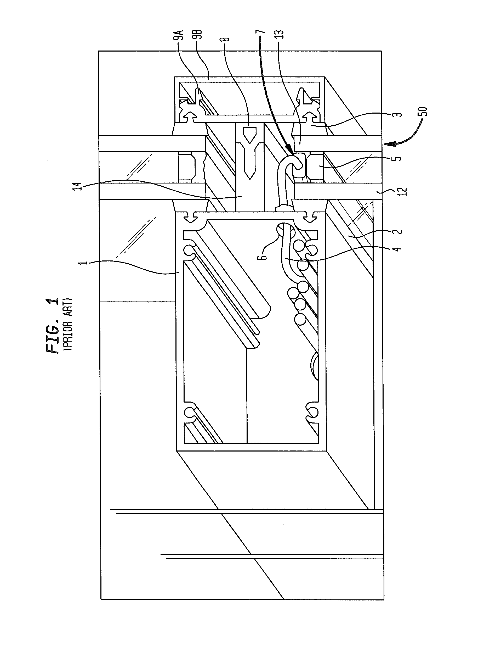
[0052]In this example frame systems shown in FIGS. 2A-2C, the frame 1 within an interior of a building may be in sealed engagement with the inner seal 2 of the IGU 50. The frame 1 may further have a protruding member 14 in sealed engagement with ...


PUM


Abstract

A system for providing an electrical interface across a sealed boundary may include a frame in sealed engagement with at least a portion of a substrate. The substrate may be in communication with an electrochromic device. The system may further include first and second conduits. The first conduit may be on a first side of the substrate and a second conduit may be on a second side of the substrate. The second conduit may be in communication with the first conduit through at least one of the seal, a space between the seal and the frame, and a space between the seal and the substrate.

Description

CROSS-REFERENCE TO RELATED APPLICATIONS[0001]The present application is a continuation of U.S. patent application Ser. No. 13 / 610,143 filed Sep. 11, 2012, which claims the benefit of the filing date of U.S. Provisional Patent Application No. 61 / 589,024 filed Jan. 20, 2012, the disclosures of which are hereby incorporated herein by reference.FIELD OF THE INVENTION[0002]The present invention relates to architectural glazing frame systems and more particularly to electrical connectivity within architectural glazing frame systems.BACKGROUND OF THE INVENTION[0003]Insulated glass units (IGUs) include opposing glass lite panels separated by a spacer along the edge in which the spacer and the glass sheets create a seal around a dead air space (or other gas, e.g. argon, nitrogen, krypton). A series of thin films, known as electrochromic glazings, are applied or deposited to one of the glass lite panels. Electrochromic glazings include electrochromic materials that are known to change their o...

Claims


Application Information

Patent Timeline
Patent Type & Authority Applications(United States)
IPC IPC(8): H02G3/30
CPCG02F1/1533G02F2201/42G02F1/161H04B5/0037H02G3/30E06B2009/2464E06B3/04E06B3/6722
Inventor SNYKER, MARK O.GREER, BRYAN D.
Owner SAGE ELECTROCHROMICS
Why Eureka
Try Eureka