System and methods for daylight-integrated illumination control

a control system and daylight-integrated technology, applied in the field of light detectors, can solve the problems of optimum control and often low illumination level, and achieve the effects of simple solution, enhanced accuracy of results, and low cos

Inactive Publication Date: 2014-02-13
KONINKLIJKE PHILIPS ELECTRONICS NV
View PDF1 Cites 17 Cited by
  • Summary
  • Abstract
  • Description
  • Claims
  • Application Information

AI Technical Summary

Benefits of technology

[0011]The present calculator provides for a simple, low-cost solution for determining daylight illumination level and illumination contribution from different luminaires simultaneously. The present detector structure having an electronic filter for preparing the illumination signal for the estimations provides for such a simple solution. Furthermore, the separate determination of the DC components from daylight and from artificial light and the subsequent combining of the results provides for an accurate determination of the daylight contribution and the artificial light contribution. Additionally, by using the present dimming levels and modulation depths when estimating the artificial li...

Problems solved by technology

On the other hand, by turning off the luminaries the illumination level often becomes t...

Method used


Image

  • System and methods for daylight-integrated illumination control
  • System and methods for daylight-integrated illumination control
  • System and methods for daylight-integrated illumination control

Examples


Embodiment Construction

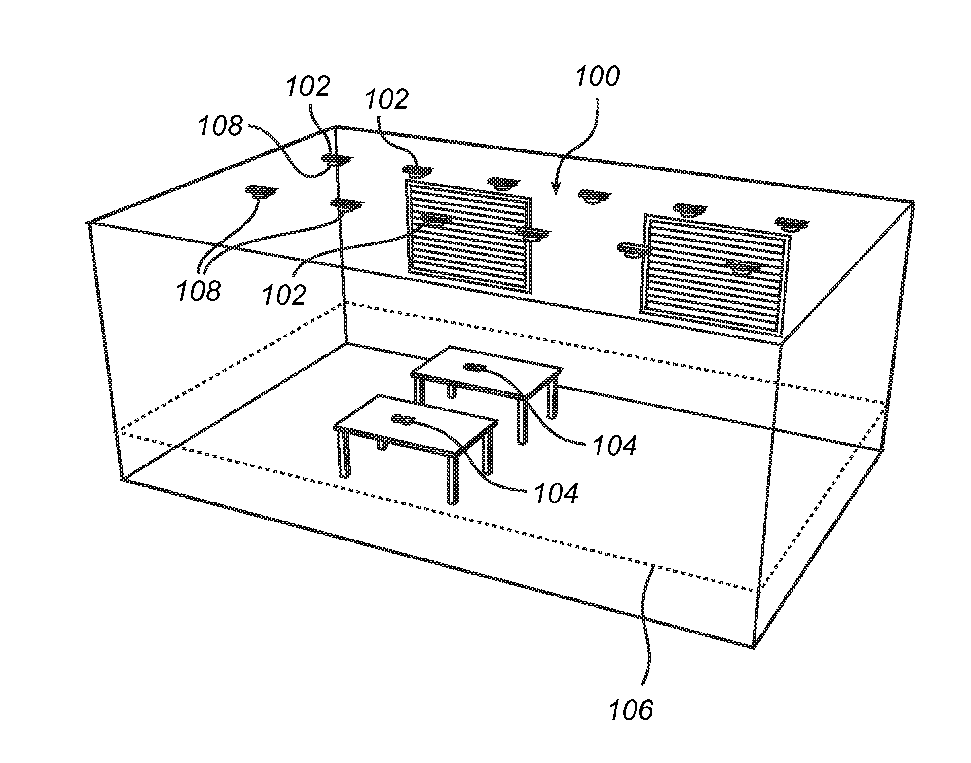
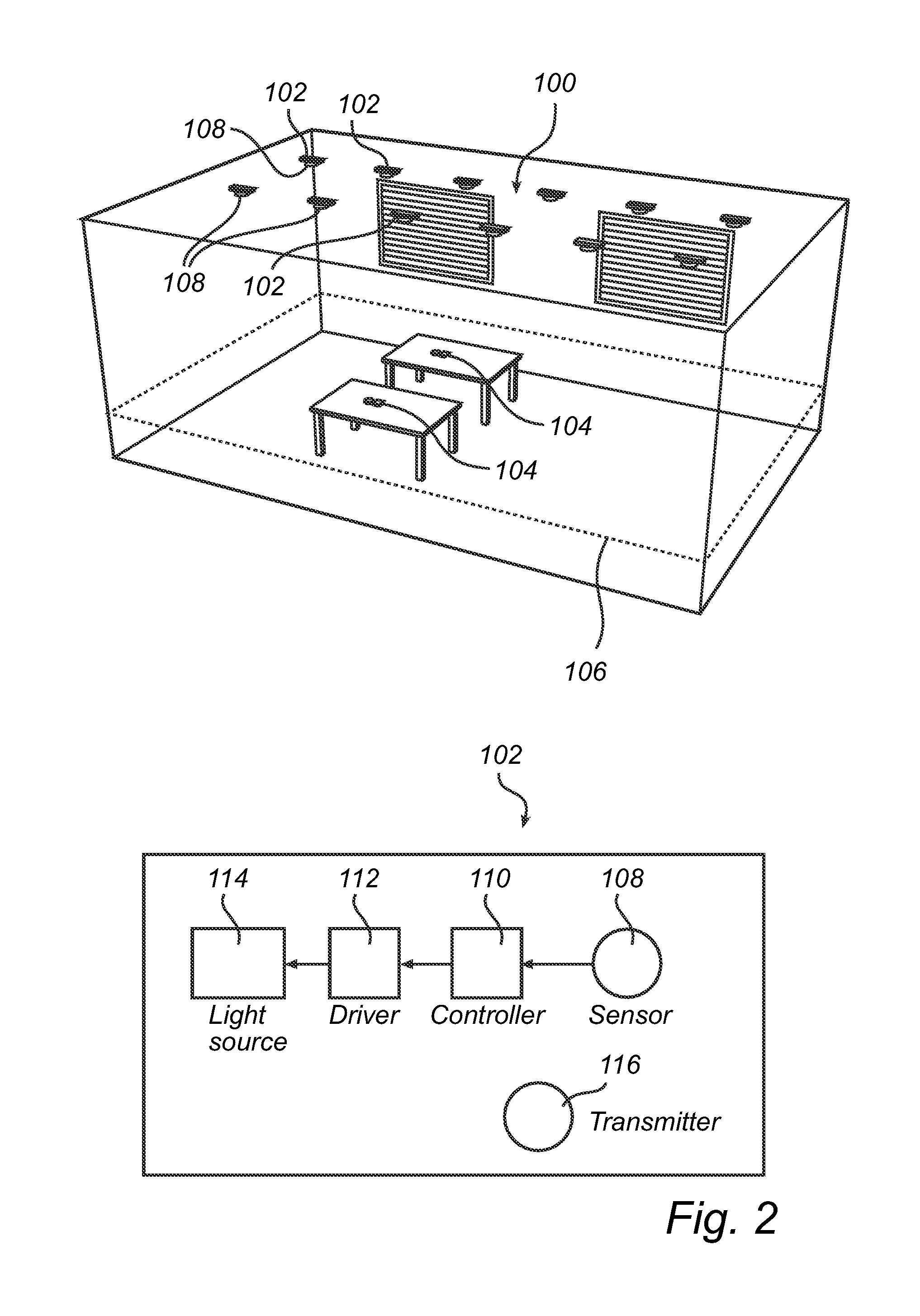
[0044]Referring to FIG. 1 and, a first embodiment of the lighting system 100 comprises several luminaires 102 arranged at a ceiling of a room, and several light detectors 104 arranged in target positions at a workspace plane 106 of the room. For instance the target positions can be at desks. Each luminaire comprises a sensor 108, a controller 110 connected with the sensor 108, a driver 112 connected with the controller 110, and a light source 114 connected with the driver 112. The controller 110 is arranged to receive signals from the light detectors 104 via the sensor 108, and to control the light source 114 via the driver 112.

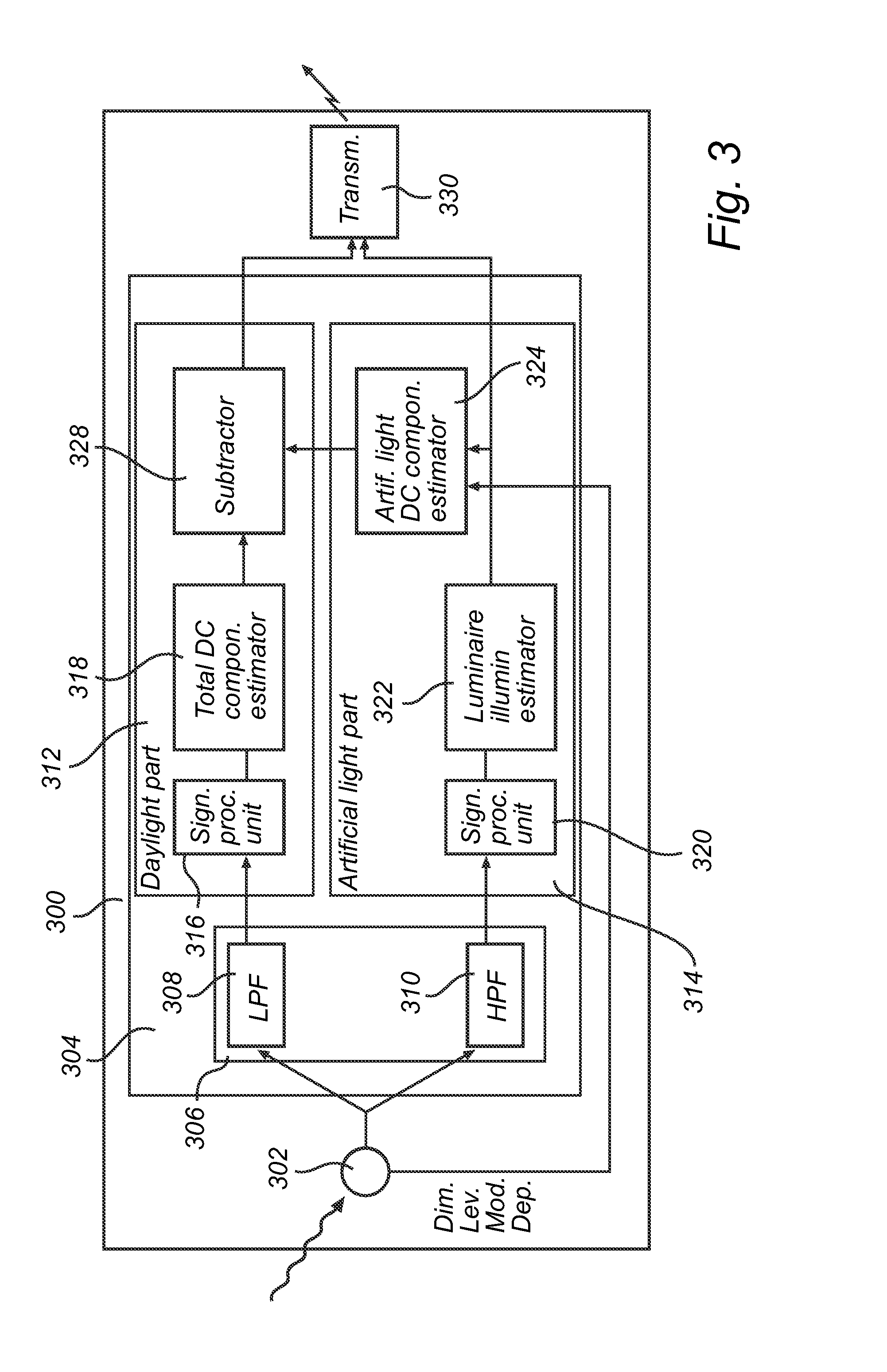
[0045]According to a first embodiment of the light detector 300 as shown in FIG. 3 it comprises a photo sensor 302, which is arranged to detect the illumination level at its position, and to output a corresponding illumination signal, and a calculator 304, connected with an output of the photo-sensor 302 for receiving the illumination signal. The calculator 3...


PUM


Abstract

A light detector arranged to determine a daylight contribution and an artificial light contribution to a combined illumination level wherein the artificial light comprises individual light coding modulation. The detector comprises:—a photo-sensor arranged to detect the illumination level at its position, and generate an illumination signal; and—a calculator, connected with the photo-sensor for receiving the illumination signal, and arranged to calculate the daylight contribution and the artificial light contribution and output corresponding daylight and artificial light signals. The calculator comprises:—an electronic filter arranged to prepare the illumination signal for estimation of the daylight and artificial light contributions;—a daylight part and an artificial light part, respectively connected to the electronic filter. The artificial light part comprises an artificial light DC component estimator, and the daylight part comprises a total DC component estimator, and a subtractor connected to the total DC component estimator and to the artificial light DC component estimator, and being arranged to determine the daylight contribution as the difference between their outputs. The artificial light DC component estimator is arranged to include present luminaire dimming level data and modulation depth data regarding the light coding modulation in a basis of its estimation.

Description

FIELD OF THE INVENTION[0001]The present invention relates to a light detector, a lighting system comprising at least one such light detector and at least one luminaire, and a method of controlling a lighting system.BACKGROUND OF THE INVENTION[0002]Efforts have been made to save energy by controlling the dim level of dimmable luminaries, e.g. dimmable light emitting diode (LED) luminaires, in a room. When a lot of daylight or other external light enters the room there is usually no need for a full power of the luminaries. On the other hand, by turning off the luminaries the illumination level often becomes too low. By properly controlling the dimming levels of the luminaires it is possible to provide a partial illumination, which in combination with the illumination already provided by daylight renders a sufficient total illumination, e.g. in terms of users' needs or lighting norms.[0003]To realize daylight-integrated control of a distributed lighting system, it is necessary to make ...

Claims


Application Information

Patent Timeline
IPC IPC(8): G01J1/44H05B33/08H05B44/00
CPCH05B37/0218Y02B80/50Y02B20/46H05B33/0854G01J1/44H05B47/11Y02B20/40H05B45/12
Inventor YANG, HONGMINGPANDHARIPANDE, ASHISH VIJAYPENNING DE VRIES, HENDRICUS THEODORUS GERARDUS MARIA
Owner KONINKLIJKE PHILIPS ELECTRONICS NV
Why Eureka
Try Eureka