
Fail-safe alarm activation system

a technology of alarm activation system and failure to meet safety requirements, applied in the direction of optical radiation measurement, instruments, counting objects on conveyors, etc., can solve the problems of non-performance of the system, serious injury to patients or staff members, and missed dangerous threats

Inactive Publication Date: 2014-02-13
MEDNOVUS
View PDF7 Cites 2 Cited by
  • Summary
  • Abstract
  • Description
  • Claims
  • Application Information

AI Technical Summary

Benefits of technology

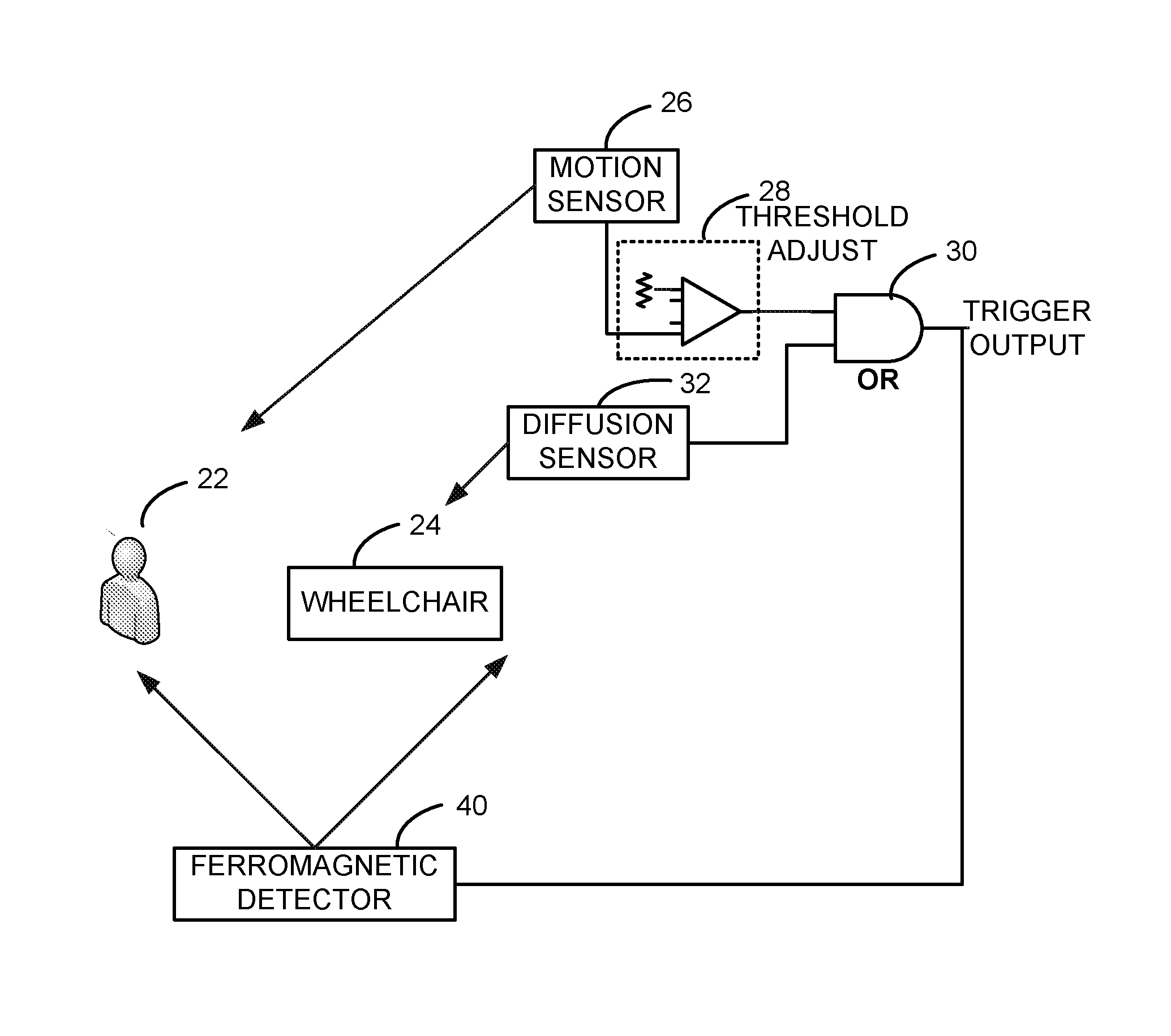
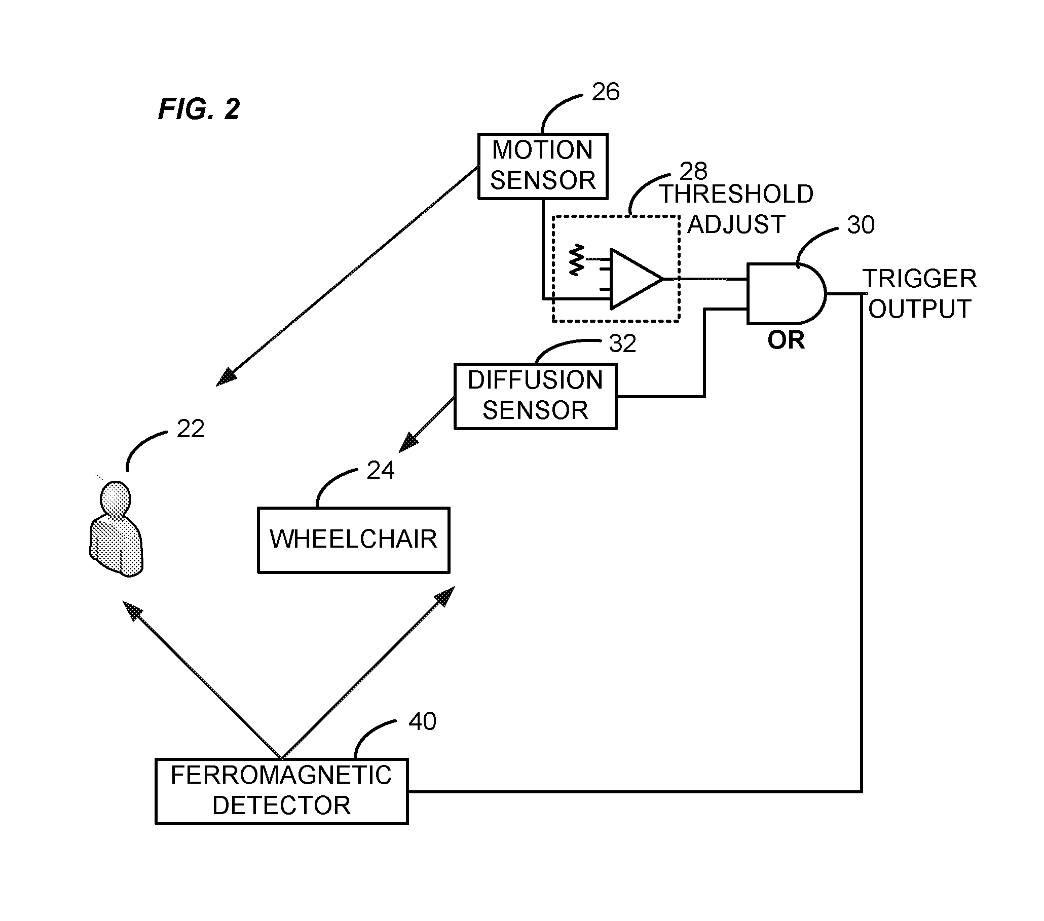
The present invention solves the problem of non-performance and false negative detections in metal detector systems used for pre-MRI safety screening. The invention utilizes both a photo-beam detector and a motion detector to detect ferromagnetic threat objects and prevent accidents. The system is designed to activate the alarm and place the detector into the ready-to-alarm mode when a ferromagnetic object is detected. The invention avoids the use of infrared diffusion photo beams that can be blocked by certain objects, such as black-denim jeans or chrome wheel chairs, and ensures that both heat-producing humans and non-heat producing objects are detected. The invention is particularly useful in medical facilities where ferromagnetic objects can be dangerous.

Problems solved by technology

It is problematic with metal detector systems, including ferromagnetic detectors used for pre-MRI safety screening, that dangerous threats can be missed because the ferromagnetic pass-through detection system in certain circumstances is not placed into the activated “ready-to-alarm” mode required to alarm on such threats.
This result is non-performance of the system and a false negative “miss” which could seriously injure a patient or staff member.
And it is undesirable to leave the detector continuously in the activated “ready to alarm” mode, because unwanted alarms would be occurring constantly—and even when patients, staff, or instrumentation were not traversing the designated alarm pathway of the detector system.
This extreme annoyance would cause most facilities to simply turn off the system, thereby losing all benefit of this line of defense against projectile missile threats.

Method used


Image

  • Fail-safe alarm activation system
  • Fail-safe alarm activation system
  • Fail-safe alarm activation system

Examples


Embodiment Construction

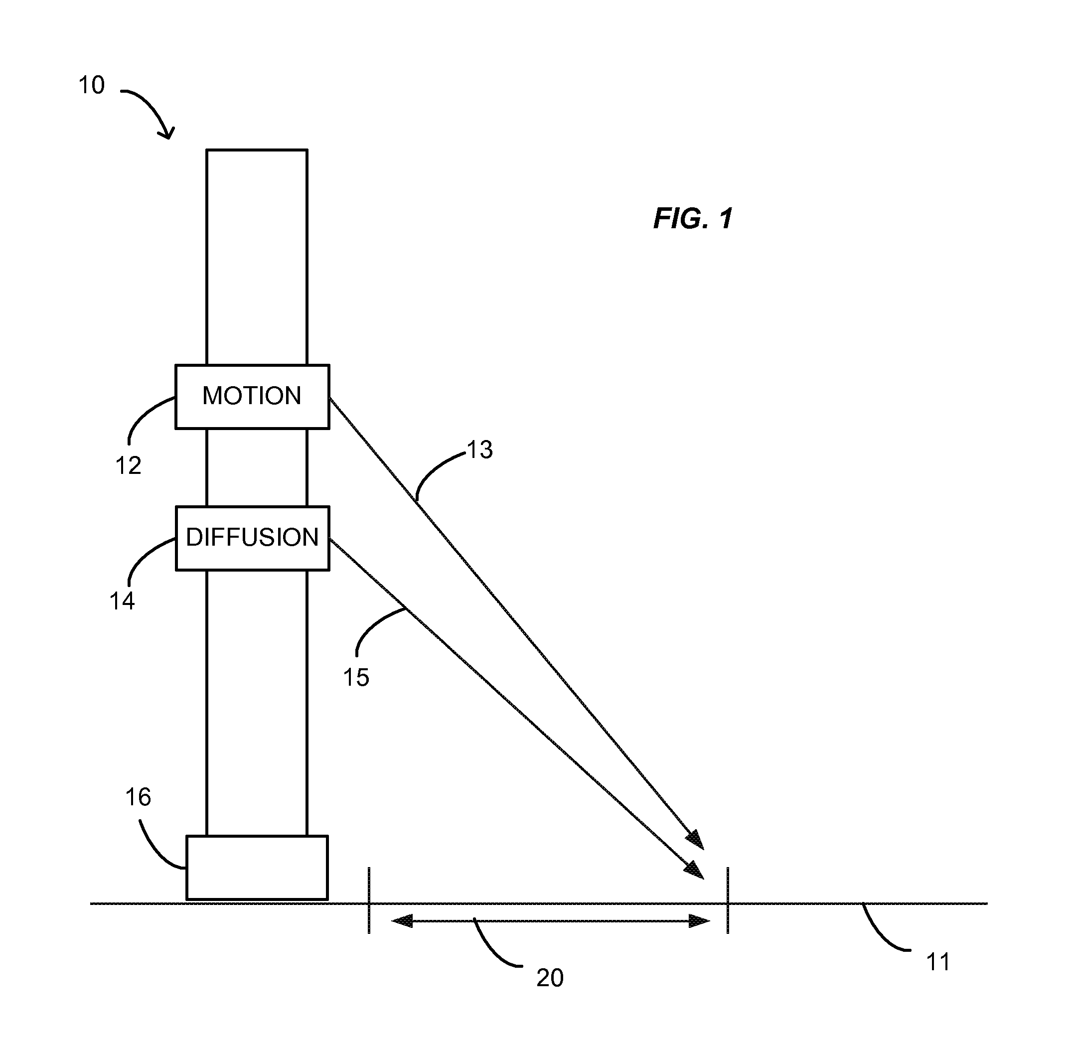
[0028]As shown in FIG. 1, the present invention may be embodied in a pillar 10 resting on a floor 11. It will be understood that the pillar 10 may be embodied in a number of ways, with the only requirement being that the same, or a combination of the same, hold two detectors of different types, e.g., a motion detector 12 and a diffusion-type photo-beam detector 14, such that the same have respective lines of sight 13 and 15 gazing at a sensing aperture 20. In more detail, lines 13 and 15 represent centerlines of the fields of view of the different respective sensor-based detectors. The pillar 10 may rest on a base 16, or alternatively, may be mounted on the wall.

[0029]The diffusion photo-beam detector 14 may detect infrared (IR) and is sensitive to reflections emanating from objects, those both moving and stationary. Objects such as chairs and light-colored clothing which reflect have a better chance of being sensed. Dark objects, however, such as black carts, or subjects wearing bl...


PUM

PropertyMeasurementUnit
thresholdaaaaaaaaaa
heataaaaaaaaaa
Magnetic Resonance Imagingaaaaaaaaaa

Abstract

The present invention provides an apparatus and method for ensuring that a pass-by detector system is placed in “ready-to-alarm” mode when a subject carries a ferromagnetic threat, or an inanimate ferromagnetic object independent of a human subject passes within the physical zone designated for alarming to such a threat. A fail-safe alarm system consisting of dual detection systems solves the failure of motion-detection systems when confronted with non-heat producing ferromagnetic threat objects; and the failure of photo-beam detection systems when confronted with black, non-reflective clothing. Applications for the present invention include pre-MRI safety screening, as well as certain security protocols, such as banks, schools, prisons, and courthouses.

Description

BACKGROUND OF THE INVENTION[0001]1. Field of the Invention[0002]This invention is in the field of magnetic resonance safety screening for dangerous ferromagnetic threat objects, with applications for security screening, such as banks, schools, and courthouses.[0003]2. Background Art[0004]Magnetic Resonance Imaging (MRI) has been called “the most important development in medical diagnosis since the discovery of the x-ray” over 100 years ago, with an estimated 8,200 MRI facilities in the U.S. and an additional 15,000 overseas. Companies selling MRI systems include GE Healthcare, Siemens, Philips, Toshiba, Fonar, and Hitachi. It is estimated that 28 million MRIs are performed per year in the United States.[0005]MRI is a less invasive diagnostic modality than x-ray imaging, since it involves no ionizing radiation. It is safer than positron emission tomography (PET), involving no ingestion of radioactive isotopes. Although touted as an inherently safe diagnostic procedure, MRI does carry...

Claims


Application Information

Patent Timeline
Patent Type & Authority Applications(United States)
IPC IPC(8): G01N21/84G08B13/02G01J5/00
CPCG01J5/06
Inventor HOLOWICK, ERWINMASSENGILL, R. KEMP
Owner MEDNOVUS
Learn More