Method and device for the rapid oil change on drive devices of wind power plants

a technology of drive device and wind power plant, which is applied in the direction of machines/engines, stators, liquid fuel engines, etc., can solve the problems of high cost, large expenditure, and contamination of oil, and achieve the effects of accelerating oil change, reducing time consumption and cost of personnel, and reducing the cost of an oil change or the maintenance of wind power plants

Active Publication Date: 2014-02-13
SENVION GMBH
View PDF6 Cites 8 Cited by
  • Summary
  • Abstract
  • Description
  • Claims
  • Application Information

AI Technical Summary

Benefits of technology

[0007]An advantage of the invention is reducing time consumption and cost of personnel for an oil change in wind power plants and ultimately to reduce the costs of an oil change or of the maintenance of wind power plants.
[0008]A solution according to the invention lies in the features as broadly described herein. Advantageous developments are subjects of the detailed embodiments described below.
[0009]Proposed is a method and an arrangement, with which the method can be carried out, that can accelerate the oil change on wind power plants and also reduce the personnel cost. The disclosure also extends to correspondingly designed drive devices and to an oil change device.
[0010]In the case of a method for carrying out an oil change on a wind power plant, which has a tower with an engine nacelle located thereupon on which a rotor with a plurality of rotor blades is rotatably attached and the rotor has a plurality of drive devices arranged with different orientation, comprising rotating of the wind-powered rotor into a maintenance position, subsequent draining of the oil from a first drive device, filling of the first drive device with fresh oil, draining of the oil from a second drive device, which is oriented differently to the first drive device, and filling of the second drive device with fresh oil, it is provided according to the invention that a first closable outlet opening on a sump of the first drive device is rotated into a geodetic low point in the maintenance position of the rotor and the drive devices, on an end of their housing opposite the sump, have in each case a mirrored sump with a second closable outlet opening, wherein the draining of the oil from the second drive device is carried out by means of the second closable outlet opening so that the rotor, during and between the draining of oil from the first drive device and second drive device, can maintain its rotated position.
[0011]Some of terms used may be explained below.
[0012]That rotated position of the wind-powered rotor in which an oil change is to be carried out is understood by a maintenance position. Thus, the so-called Y-position, in which one of the rotor blades is oriented vertically downward, can be defined as the maintenance position for a three-bladed rotor, for example. In the case of correspondingly positioned outlet openings, each of the other rotor positions can also be used as the maintenance position.

Problems solved by technology

As a result of abrasion, the oil becomes contaminated and has to be changed regularly in the course of a maintenance.
This requires the presence of a fitter in the engine nacelle of the wind power plant, which necessitates considerable expenditure especially in the case of a large number of wind power plants in a wind farm and / or in the case of wind power plants which are installed a distance away, for example in the case of offshore wind power plants.
The high cost as a result of the repeated rotation of the wind-powered rotor, which requires a lot of time for one thing and a large number of personnel for another thing, is the disadvantage of this method.
This device, however, is quite large and heavy and because of this is not suitable for portable use.
It is therefore unsuitable for use during maintenance of wind power plants.

Method used


Image

  • Method and device for the rapid oil change on drive devices of wind power plants
  • Method and device for the rapid oil change on drive devices of wind power plants
  • Method and device for the rapid oil change on drive devices of wind power plants

Examples


Embodiment Construction

[0039]The invention is explained based on an example of a wind power plant with three rotor blades.

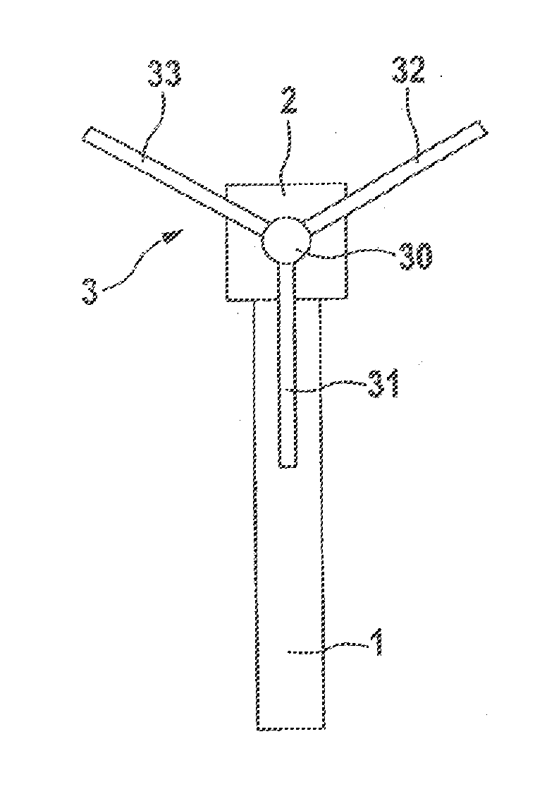
[0040]FIG. 1 shows the schematic construction of a wind power plant. It has a tower 1 with an engine nacelle 2. The end face of the engine nacelle 2 has a rotatably mounted rotor 3. The rotor 3 has a rotor hub 30 on which two rotor blades, or a plurality of rotor blades 31, 32, 33, are adjustably arranged. For this exemplary embodiment, a position of the rotor 3, in which one of the rotor blades 31 is oriented vertically downward, is defined as the maintenance position, as shown in FIG. 1.

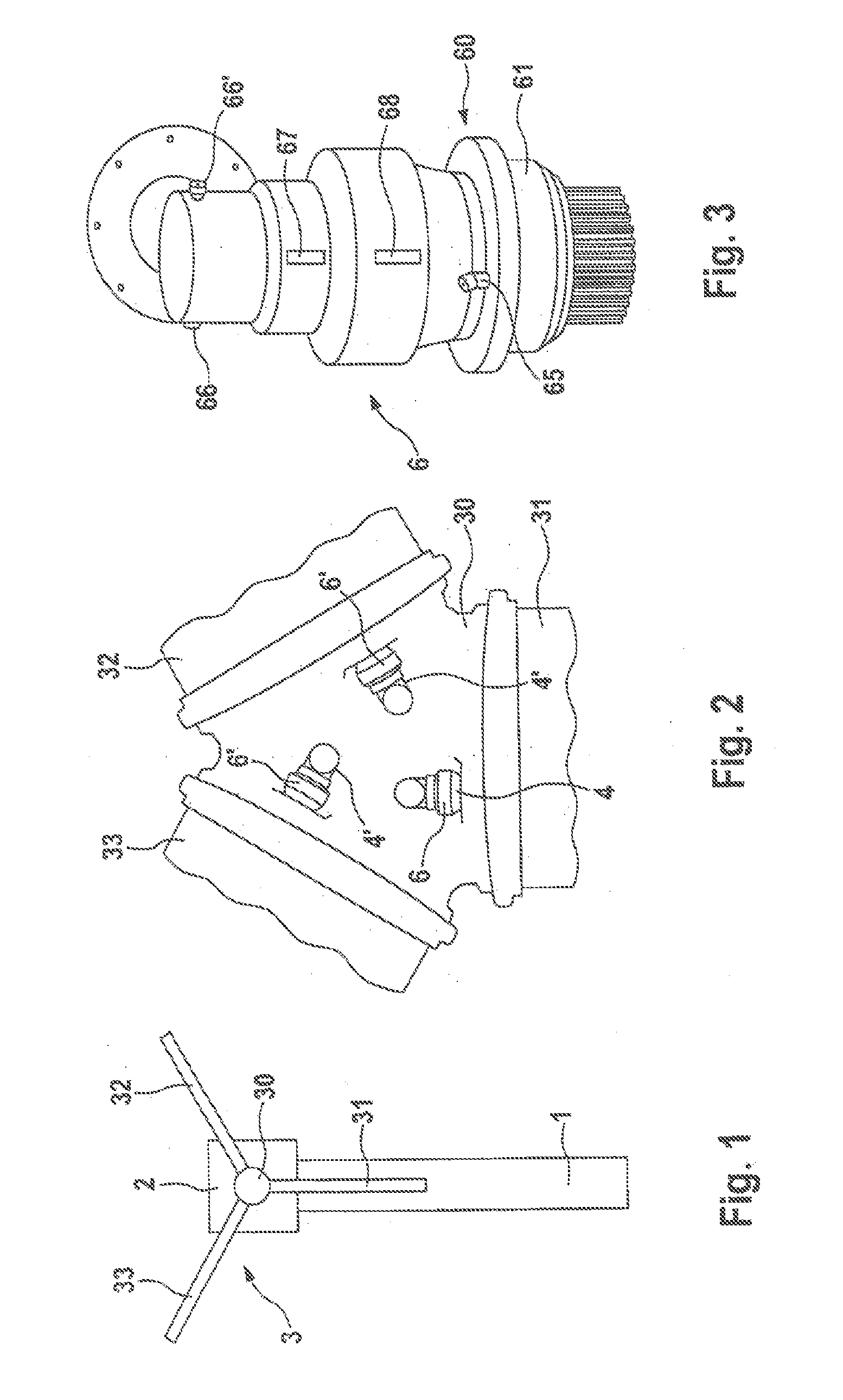
[0041]Arranged in the rotor hub 30 are a plurality of drive devices 6, 6′, of which there are three in the exemplary embodiment, with which the incidence angle of the rotor blades 31, 32, 33 can be adjusted. Each of these drive devices 6, 6′ is associated with one of the rotor blades 31-33.

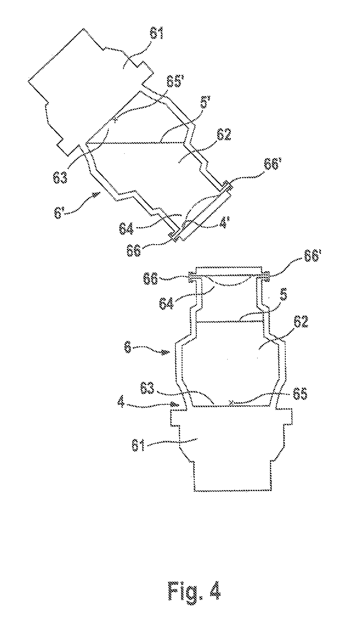
[0042]The drive devices 6, 6′ have a housing 60 with a flanged-on driving head 61. The housing 60 encloses an oil...


PUM


Abstract

The invention relates to a method for performing an oil change on a wind power plant, comprising the steps of rotating the rotor (3) to a maintenance position, subsequently draining the oil out of a first variable-speed gearbox (6), filling the first variable-speed gearbox (6) with fresh oil, draining the oil out of a second variable-speed gearbox (6′) that is oriented differently than the first gearbox, and filling the second drive device (6′) with fresh oil. The variable-speed gearboxes each comprise a sump (63) having a first outlet opening (65) and a mirrored sump (64) on the opposite end of the housing thereof having a second outlet opening (66). Thus, the rotor (3) does not need to be rotated further during the oil change. The oil change can be performed simultaneously on several or all variable-speed gearboxes, reducing time and personnel expenses. The invention further relates to a correspondingly designed drive device and to an oil changing device.

Description

REFERENCE TO RELATED APPLICATIONS[0001]This application is a national stage application under 35 USC 371 of International Application No. PCT / EP2012 / 054158, filed Mar. 9, 2012, which claims the priority of German Application No. 10 2011 015858.8, filed Apr. 1, 2011, the entire contents of which are incorporated herein by reference.FIELD OF THE INVENTION[0002]The invention relates to oil changes on drive devices of wind power plants, especially motors and gearboxes for pitch adjustment devices.BACKGROUND OF THE INVENTION[0003]Modern wind power plants customarily have a wind-powered rotor, the rotor blades of which are variable with regard to their angle of incidence (so-called pitch adjustment). To this end, drive devices are provided on the wind-powered rotor. As a rule, the drive devices are arranged in the rotor hub, wherein for reasons of power output and redundancy a separate drive device is associated with each rotor blade.[0004]In general, drive devices, such as gearboxes and ...

Claims


Application Information

Patent Timeline
Patent Type & Authority Applications(United States)
IPC IPC(8): F03D7/00
CPCF03D7/00F03D80/50F03D80/70F05B2260/602F05B2260/79F05B2260/98Y02E10/72
Inventor SCHNETGOEKE, HANNOTUBBESING, ANDRE
Owner SENVION GMBH
Why Eureka
Try Eureka