Ceiling Fan Blade

a ceiling fan and blade technology, applied in the field of ceiling fan blades, can solve the problems that the external appearance of the conventional ceiling fan has to be improved, and achieve the effect of maintaining a smooth and pretty external appearan

Active Publication Date: 2014-02-13
AIR COOL INDAL
View PDF1 Cites 15 Cited by
  • Summary
  • Abstract
  • Description
  • Claims
  • Application Information

AI Technical Summary

Benefits of technology

[0008]The ceiling fan blade of this invention is to have the locking base of the locking plate protruding out of the reverse side of the blade for securing the blade on the blade holder by the locking member. Thus, there is not any locking member on the downward obverse side of the ceiling fan blade, enabling the ceiling fan blade to maintain a smooth and pretty external appearance.

Problems solved by technology

Therefore, the defect of external looks of the conventional ceiling fan has to be improved.

Method used


Image

  • Ceiling Fan Blade
  • Ceiling Fan Blade
  • Ceiling Fan Blade

Examples


Embodiment Construction

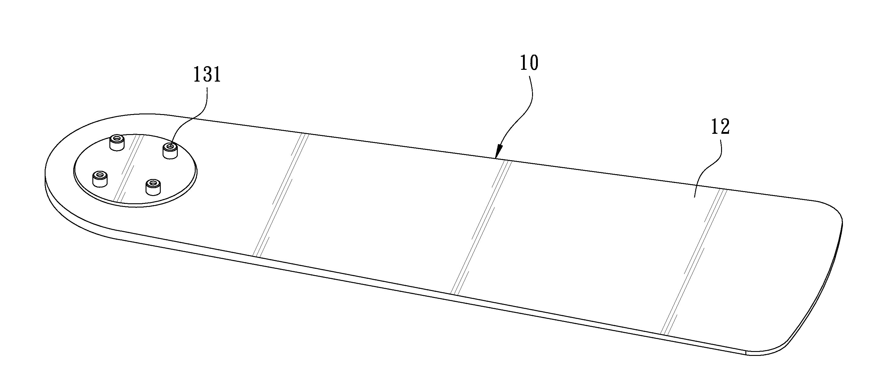
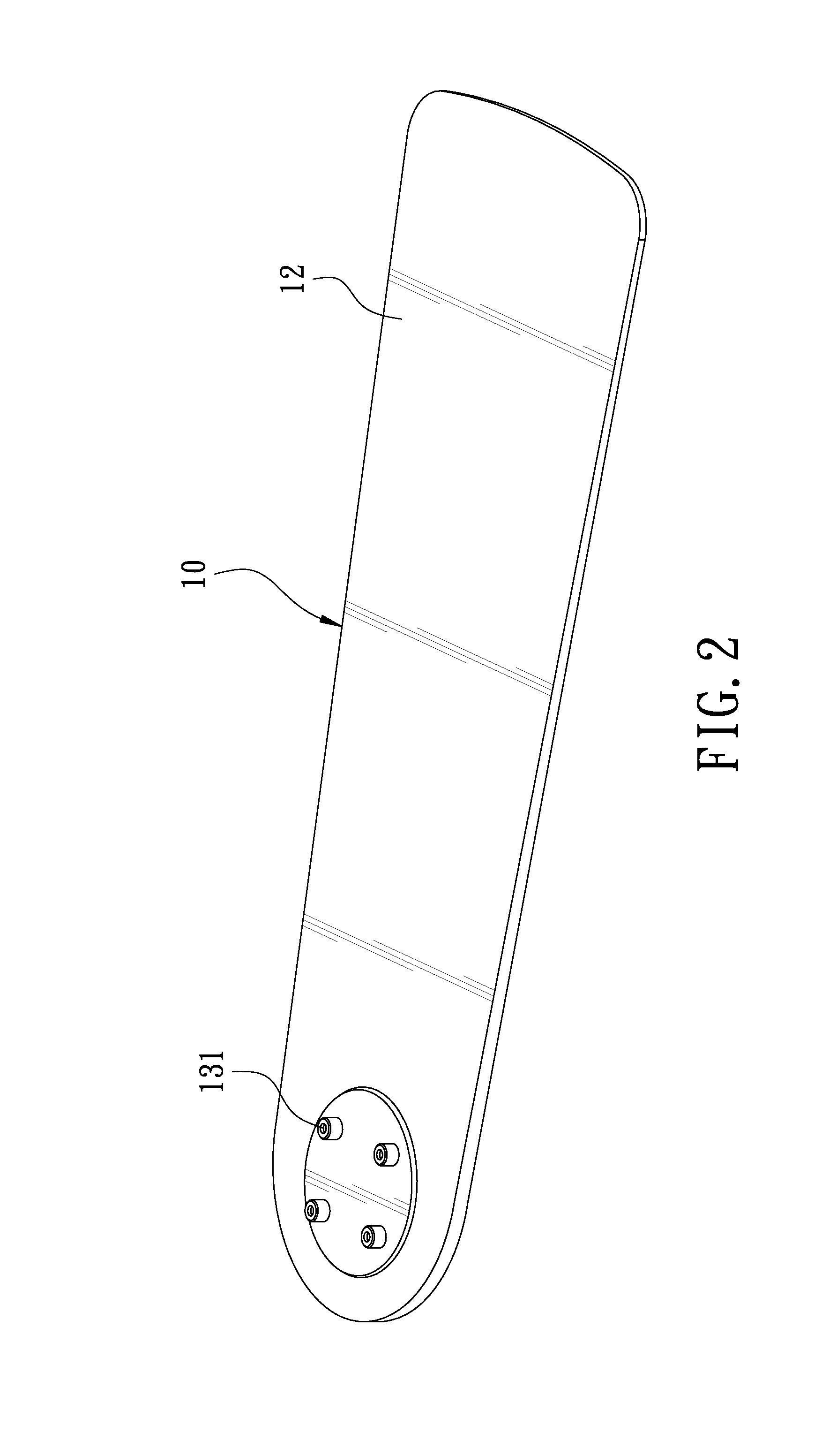
[0015]A preferred embodiment of a ceiling fan blade in the present invention, as shown in FIGS. 2, 3 and 4, includes a blade 10, a blade holder 20 and four locking members 30 combined together.

[0016]The blade 10 has one side facing downward defined to be an obverse side 11 and another side facing upward defined to be a reverse side 12, and a locking plate 13 is embedded in the interior of the blade 10 and bored with a longitudinal through hole 132 so that when the locking plate 13 is embedded in the blade 10 during the blade 10 is being shaped, the space in the through hole 132 can be filled up for reinforcing the combined strength of the locking plate 13 and the blade 10. The locking plate 13 is provided thereon with four locking bases 131, which are respectively a stud 1311 having a bottom side annularly formed with a flange 1313. The locking plate 13 is further disposed with four through holes 133 for the four locking bases 131 to be respectively inserted and fixed therein, and t...


PUM


Abstract

A ceiling fan blade includes a blade having at least one locking plate embedded in the interior. The locking plate is provided thereon with at least one locking base protruding out of the reverse side of the blade. A blade holder to be locked with the blade is bored with a locking hole at a location corresponding with the locking base for the locking base to be inserted therein. The blade is firmly locked on the blade holder via at least one locking member. By so designing, there is not any locking member on the downward obverse side of a ceiling fan blade, able to maintain a smooth and pretty external appearance of the ceiling fan blade.

Description

BACKGROUND OF THE INVENTION[0001]1. Field of the Invention[0002]This invention relates to a ceiling fan blade.[0003]2. Description of the Prior Art[0004]A conventional ceiling fan generally includes a motor 1, a plurality of blades 1 and a plurality of blade holders 3 that are secured on the rotary shaft of the motor 1 for firmly combining the blades 2 and the motor together. However, in assembly of the conventional ceiling fan, at least one locking member 4 must be used for fixing the blade 2 and the blade holder 3 together. After locked, the locking member 4 will be exposed to the downward obverse side of the blade 2 to spoil the pretty external looks of the conventional ceiling fan. Therefore, the defect of external looks of the conventional ceiling fan has to be improved.[0005]Adhering to the spirit of endeavoring to do everything better and having much experience in researching and manufacturing all sorts of ceiling fans and related parts, the inventor of this invention offers ...

Claims


Application Information

Patent Timeline
Patent Type & Authority Applications(United States)
IPC IPC(8): F04D29/34
CPCF04D29/34F04D25/088F04D29/388
Inventor WANG, CLIFF
Owner AIR COOL INDAL
Why Eureka
Try Eureka