Robot device

a robot and device technology, applied in the field of robot devices, can solve the problems of reducing work efficiency, affecting the production efficiency of large-scale robot devices, and affecting the quality of robot devices, so as to achieve high versatility and not reduce work efficiency.

Active Publication Date: 2014-02-13
CANON KK
View PDF24 Cites 24 Cited by
  • Summary
  • Abstract
  • Description
  • Claims
  • Application Information

AI Technical Summary

Benefits of technology

[0008]In view of the above, the present invention has an object to provide a small-sized robot device having high versatility without decreasing the work efficiency.

Problems solved by technology

In particular, during a work that does not require positional control by the camera, the camera is only an obstacle for the arm, and the work efficiency may be reduced due to the restriction.
Further, when the camera is mounted to the arm, it is necessary to set the specification values, such as the weight capacity, of the arm to be large, and hence the downsizing of the robot device is inhibited.
Thus, there has been a problem in that it costs too much to meet large-variety production.

Method used


Image

  • Robot device
  • Robot device
  • Robot device

Examples


first embodiment

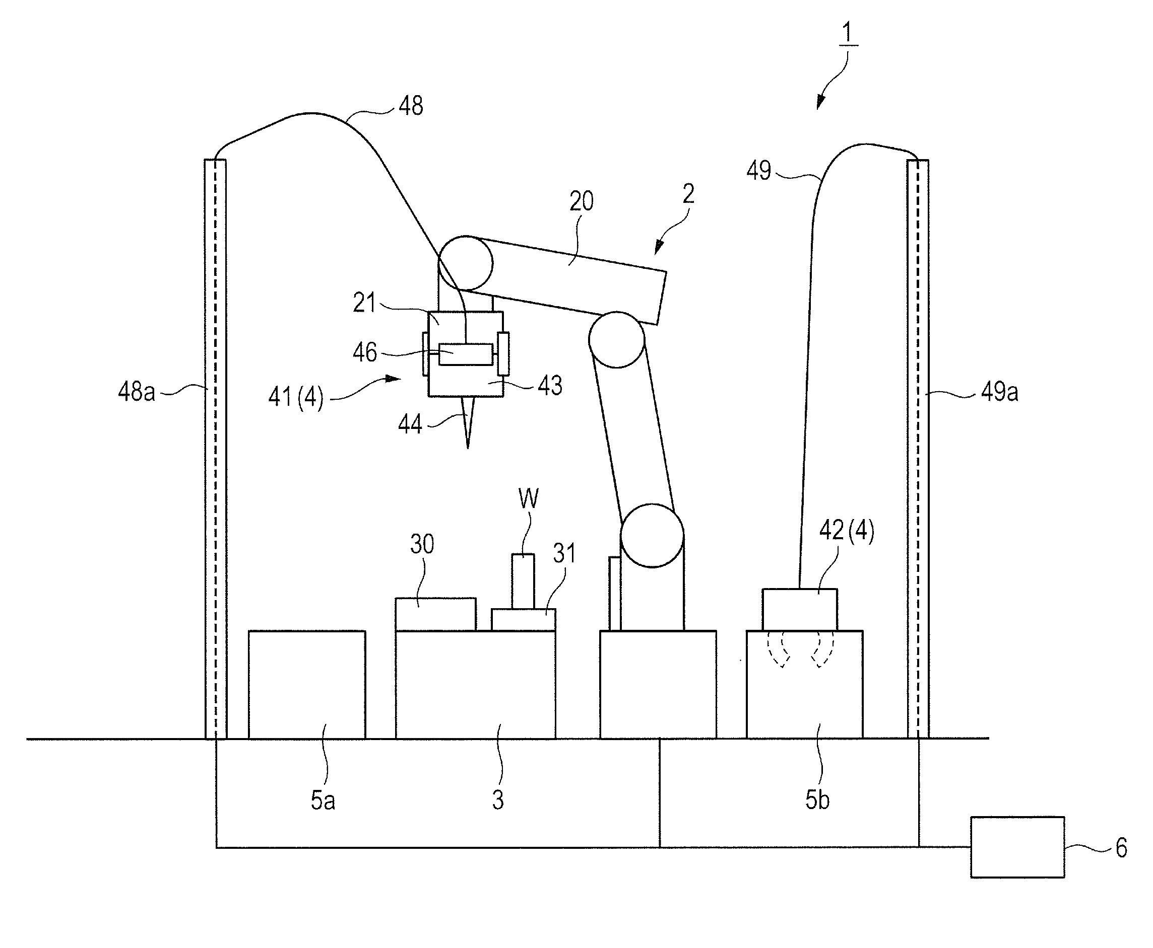
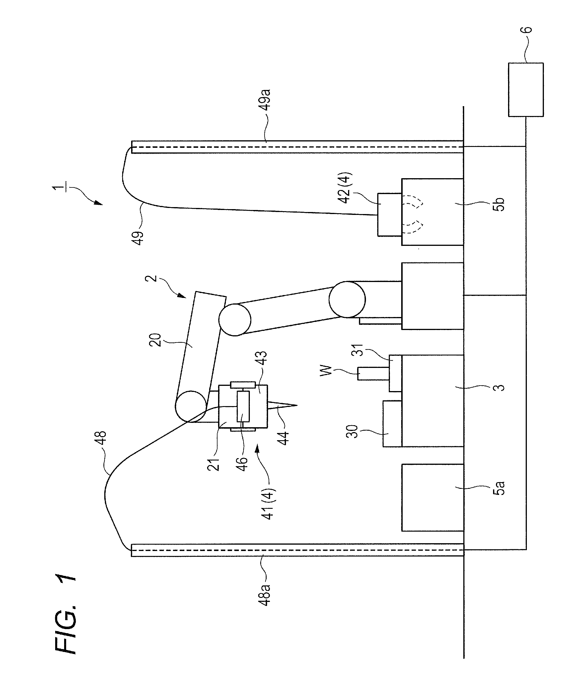
[0027]Now, a robot station 1 according to a first embodiment of the present invention is described with reference to FIGS. 1 to 4. Note that, in the following description, a hand (robot hand) refers to a member that is mounted to a distal end of an arm (robot arm) directly or through intermediation of a connecting mechanism that does not have a gripping function, and includes a mechanism with a gripping function. Further, a tool refers to a member that is used by being gripped by the hand, and includes a mechanism with a gripping function that is different from that of the hand.

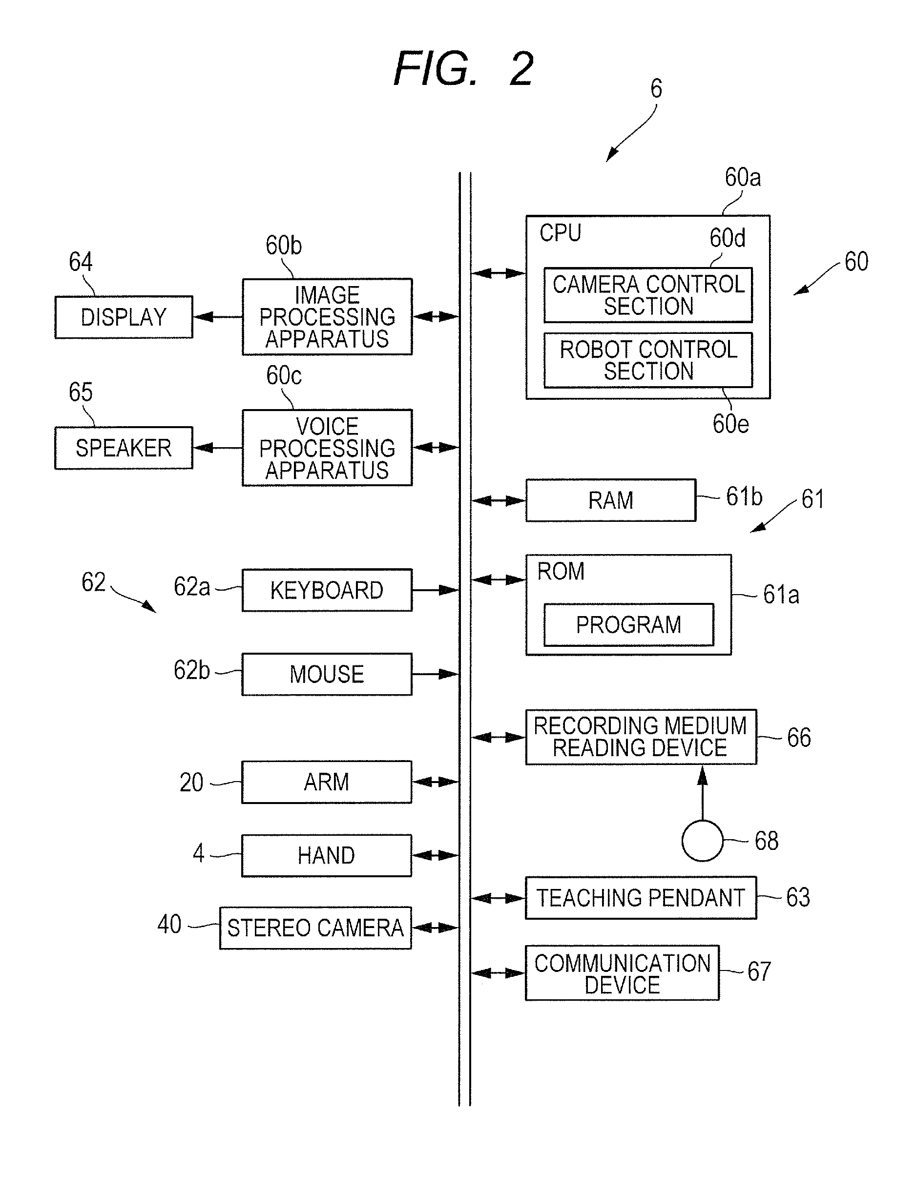
[0028]First, the schematic configuration of the robot station 1 is described with reference to FIGS. 1 and 2. FIG. 1 is a schematic view illustrating the robot station 1 according to the first embodiment of the present invention. FIG. 2 is a block diagram of a controller 6 for controlling a robot device 2 according to the first embodiment.

[0029]As illustrated in FIG. 1, the robot station 1 includes the robot ...

second embodiment

[0059]Next, a robot station 1A according to a second embodiment of the present invention is described with reference to FIGS. 5 to 8. The second embodiment is different from the first embodiment in that the hand serves as the connector. Therefore, in the second embodiment, the difference from the first embodiment, that is, the hand serving as the connector is mainly described. The same components as those in the first embodiment are represented by the same reference symbols, and description thereof is therefore omitted herein.

[0060]First, the configuration of the robot station 1A is described with reference to FIGS. 5 and 6. FIG. 5 is a schematic view illustrating the robot station 1A according to the second embodiment of the present invention. FIG. 6 is a block diagram of a controller 6A for controlling a first robot device 10 and a second robot device 2A according to the second embodiment.

[0061]As illustrated in FIG. 5, the robot station 1A includes the first robot device 10 for g...

third embodiment

[0086]Next, a robot station 1B according to a third embodiment of the present invention is described with reference to FIGS. 9 to 13. The third embodiment is different from the second embodiment in the manner of electrical connection of the tweezer tool. Therefore, in the third embodiment, the difference from the second embodiment, that is, the manner of electrical connection of the tweezer tool is mainly described. The same components as those in the second embodiment are represented by the same reference symbols, and description thereof is therefore omitted herein.

[0087]First, the configuration of the robot station 1B is described with reference to FIGS. 9 to 11B. FIG. 9 is a schematic view illustrating the robot station 1A according to the third embodiment of the present invention. FIG. 10 is a schematic view illustrating a tweezer tool 41B and a hand 21B of a second robot device 2B according to the third embodiment. FIGS. 11A and 11B are views illustrating transmission contact p...


PUM


Abstract

Provided is a small-sized robot device having high versatility without decreasing the work efficiency. The robot device includes: an arm; a hand or a tweezer tool that includes a stereo camera for measuring a three-dimensional position of a workpiece, the hand or the tweezer tool performing a work with respect to the workpiece whose three-dimensional position has been measured by the stereo camera; and a connection portion or a hand provided at a distal end of the arm, the connection portion or the hand releasably connecting the hand or the tweezer tool to the arm.

Description

BACKGROUND OF THE INVENTION[0001]1. Field of the Invention[0002]The present invention relates to a robot device including an arm, and more particularly, to a robot device including a replaceable end effector that is mounted to a distal end of an arm.[0003]2. Description of the Related Art[0004]In recent years, when a robot device is utilized to automatically assemble a precision component to a workpiece, in some cases, a tweezer hand for assembling a precision component and a camera for measuring the precision component are used to assemble the precision component while identifying the three-dimensional position of the precision component by the camera (see Japanese Patent Application Laid-Open No. 2011-011315).[0005]For example, in a robot device disclosed in Japanese Patent Application Laid-Open No. 2011-011315, a stereo camera mounted to the arm is focused on the tip of the tweezer hand, and the precision component is assembled to the workpiece while controlling the position of t...

Claims


Application Information

Patent Timeline
Patent Type & Authority Applications(United States)
IPC IPC(8): B25J9/16
CPCB25J9/1697B25J15/0433B25J19/023G06T1/0014B25J13/08
Inventor MIMURA, TOSHIHIKOARAI, TAKASHI
Owner CANON KK
Why Eureka
Try Eureka