Logic controller for railway locomotive

A technology for logic control and railway locomotives, applied to locomotives, data exchange through path configuration, signal transmission systems, etc., can solve the problems of low load capacity of DC output points, harsh working environment, and many line contacts, etc., to achieve simplified contact point control circuit, realize resource sharing, and reduce the effect of external connections

Active Publication Date: 2005-03-02
WUHAN ZHENGYUAN ELECTRIC
View PDF0 Cites 14 Cited by
  • Summary
  • Abstract
  • Description
  • Claims
  • Application Information

AI Technical Summary

Problems solved by technology

This kind of circuit has poor reliability in the working environment with heavy vibration and dust.
Especially when the speed of the locomotive increases above 120KM / h, due to the intensified vibration of the locomotive, the malfunction of the relay contact control system increases significantly
There are many line contacts, the line failure rate is high, and the disadvantages of finding and handling line failures are becoming more and more prominent
[0003] If a programmable logic controller (PLC) is used to replace the traditional relay contact control circuit, but because the locomotive relay contact control circuit has many particularities: the control voltage is DC 110V, and the maximum load current of the relay can reach nearly 5A , poor working environment, etc. According to the IEC standard, the general PLC working voltage is DC24V or AC220V, and the load capacity of the DC output point is relatively low. The multi-level driving method of the 110V intermediate relay driven by the conventional relay does not fundamentally solve the problems such as cumbersome wiring, so the general industrial PLC cannot be directly applied to the locomotive

Method used


Image

  • Logic controller for railway locomotive
  • Logic controller for railway locomotive
  • Logic controller for railway locomotive

Examples


Embodiment Construction

[0022] The present invention will be further described below in conjunction with the accompanying drawings and embodiments, but these embodiments should not be construed as limiting the present invention.

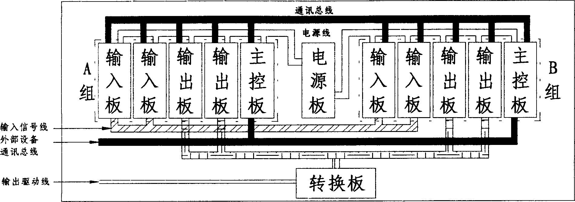
[0023] Hardware structure of the present invention ( figure 1 ) mainly includes chassis power supply, input board, output board, main control board, etc.

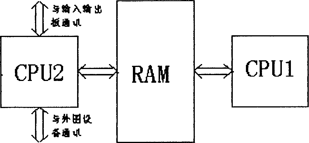
[0024] The main control board of the present invention ( figure 2 )( figure 2 ) adopts a dual-CPU structure. One CPU2 is responsible for communication with the input and output board and peripheral equipment (hereinafter referred to as communication CPU2), and the other CPU1 is responsible for logic operations and output status determination (hereinafter referred to as control CPU1). Exchange data through a dual-port RAM. The communication CPU2 puts the information of the input point state and peripheral equipment received from the input board into the dual-port RAM, and the control CPU1 reads the relevant informati...


PUM


Abstract

The logic controller for railway locomotive consists of main control board, input board, output board and power supply board, and features the bi-directional CAN bus communication among the control board, the input board and the output board, and the MOS FET driving between the output board and the electric device of the locomotive to be controlled. The present invention adopts embedded monochip computer system, CAN bus technology, and cured combination logic software in PLC logic ladder diagram structure easy to read and understand. Adopting logic control unit can simplify the design, production and debugging of locomotive control circuit, and raise the reliability of the control system. In addition, the microcomputer and electronic control system has vibration resistance obviously superior to traditional relay contact control system.

Description

[0001] The invention belongs to a railway locomotive control device, in particular to a railway locomotive logic control device. Background technique [0002] For a long time, the locomotive electrical control circuit has been using the traditional relay contact control circuit. The realization of locomotive logic relationship is accomplished through series and parallel connection of switches, auxiliary contacts of contactors, contacts of intermediate relays, time relays, pressure relays, etc. This kind of circuit has poor reliability in a working environment with a lot of vibration and dust. Especially when the speed of the locomotive increases to above 120KM / h, due to the aggravation of the vibration of the locomotive, the malfunction of the relay contact control system increases significantly. There are many line contacts, the line failure rate is high, and the disadvantages of finding and handling line failures are becoming more and more prominent. ...

Claims


Application Information

Patent Timeline
Patent Type & Authority Applications(China)
IPC IPC(8): B61C17/00G08C15/02G08C19/00H04L12/28
Inventor 易先兵陈贻堃
Owner WUHAN ZHENGYUAN ELECTRIC
Why Eureka
Try Eureka