

Method of simulating operations of non-destructive testing under real conditions using synthetic signals
- Summary
- Abstract
- Description
- Claims
- Application Information
AI Technical Summary
Benefits of technology
Problems solved by technology
Method used
Image

Examples
Embodiment Construction
[0020]This invention intends to remedy the disadvantages of the prior art by proposing a method of simulating non-destructive testing using synthetic signals.
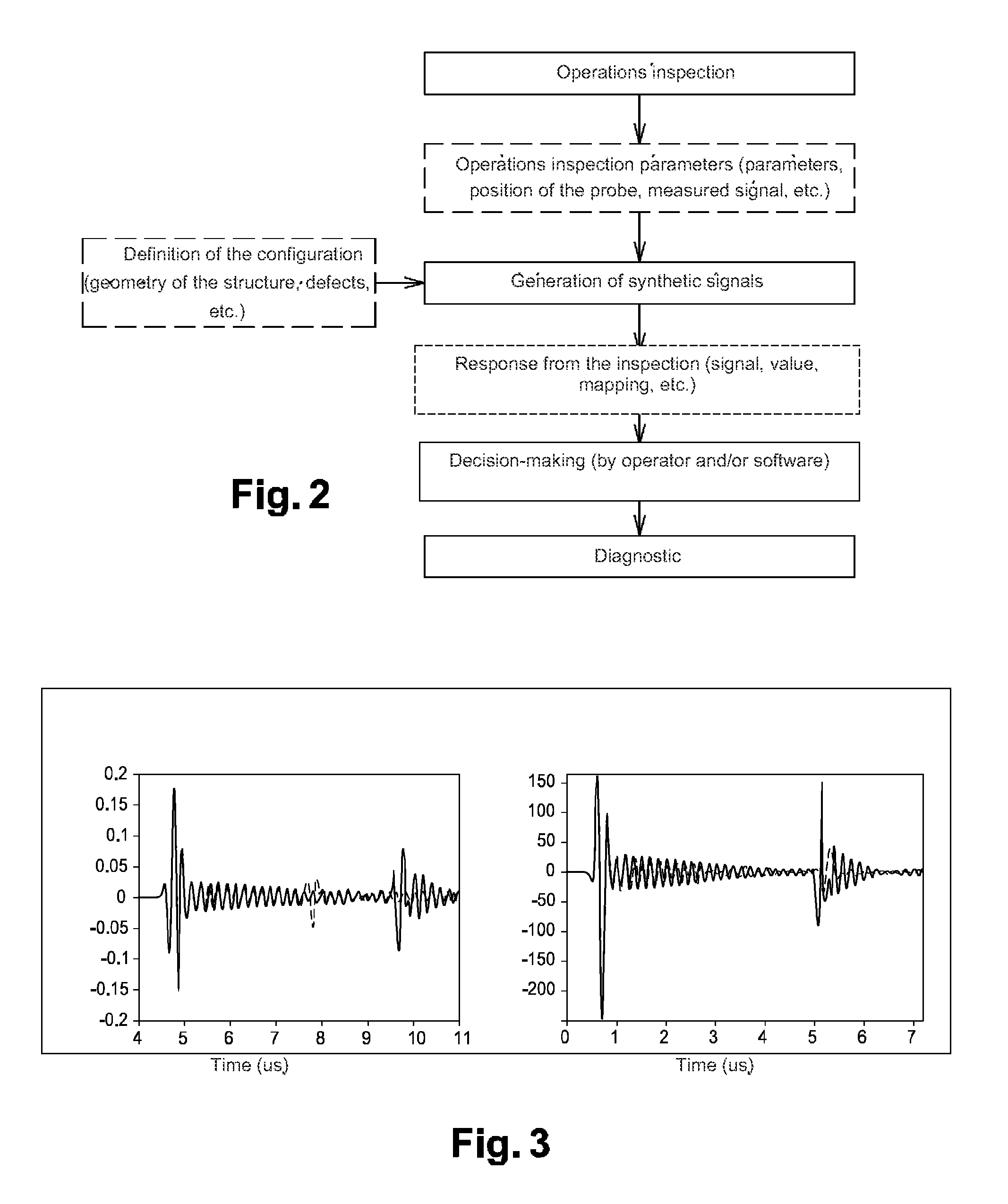
[0021]To this effect, this invention concerns, in its more general sense, a method of simulating non-destructive testing using at least one probe, characterized in that it comprises the following steps:[0022]a measurement for inspection parameters, linked to the position of said probe in the space; and[0023]a generation of synthetic signals corresponding to an operation of non-destructive testing.
[0024]According to an embodiment, said generation of synthetic signals is partly conditioned by a configuration generated by a configuration generator that consists of a virtual structure model.
[0025]Preferably, said virtual model of the structure is completed by the introduction of defects and / or by the modification of the properties of the structure elements.
[0026]According to an embodiment, said synthetic signals are measured signal...
PUM
 Abstract
Description
Claims
Application Information