Synchronized lifting and lowering apparatus

a technology of lifting and lowering apparatus and synchronization, which is applied in the direction of lifting devices, fluid-pressure actuators, servomotors, etc., can solve the problems of increasing the likelihood of causing damage to the structure, difficult operation of lifting or lowering a structure that cannot be lifted, and increasing the difficulty of lifting or lowering a structure, etc., to achieve minimal control, low cost, and simple operation.

Inactive Publication Date: 2014-02-20
ACTUANT CORP
View PDF4 Cites 4 Cited by
  • Summary
  • Abstract
  • Description
  • Claims
  • Application Information

AI Technical Summary

Benefits of technology

[0007]The present invention alleviates these needs by providing a simple, cost effective synchronized elevating system that is almost unlimited in the number of lift-points that can be used. The invention provides a low-cost, minimally controlled solution for lifting or lowering uneven loads with little technical expertise needed by the operator.

Problems solved by technology

Conversely, elevating (lifting or lowering) a structure that cannot be flexed or twisted or with uneven weight distribution, such as a slab poured on grade, is a somewhat more difficult operation.
This displacement differential may create internal stresses in the structure being elevated, increasing the likelihood of causing damage to the structure.
In addition, the displacement differential can create instability during the lift, such that the lift set up could collapse.
However, these systems, depending on the type, are typically difficult to operate, complex to assemble, and / or very expensive.
As a result, synchronized elevating of large structures is only used for high-level and complex lifting projects.
The PDFD, however, is designed to elevate at a reduced operating pressure and limited to four segments or less, typically.

Method used


Image

  • Synchronized lifting and lowering apparatus
  • Synchronized lifting and lowering apparatus
  • Synchronized lifting and lowering apparatus

Examples


Embodiment Construction

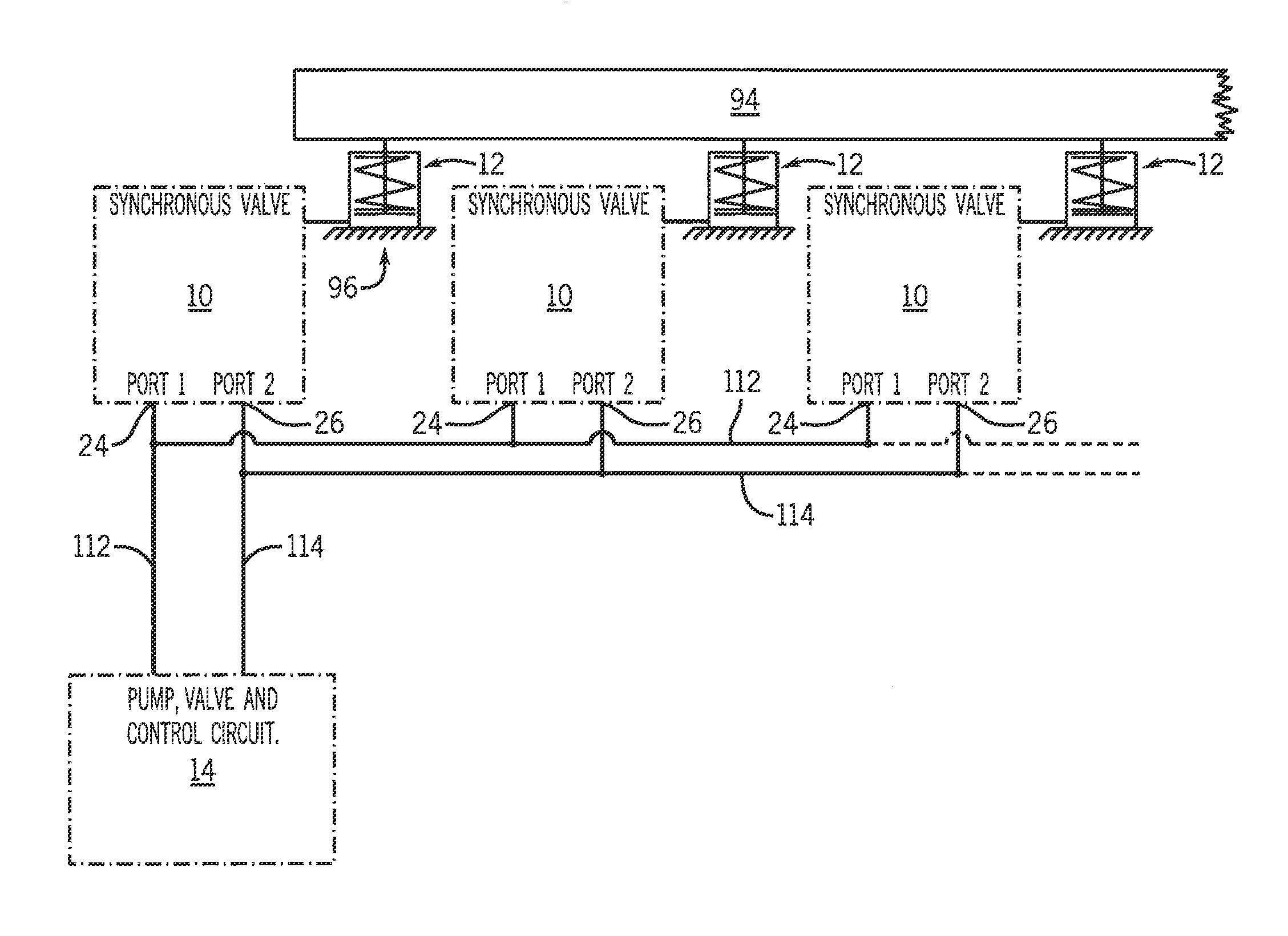
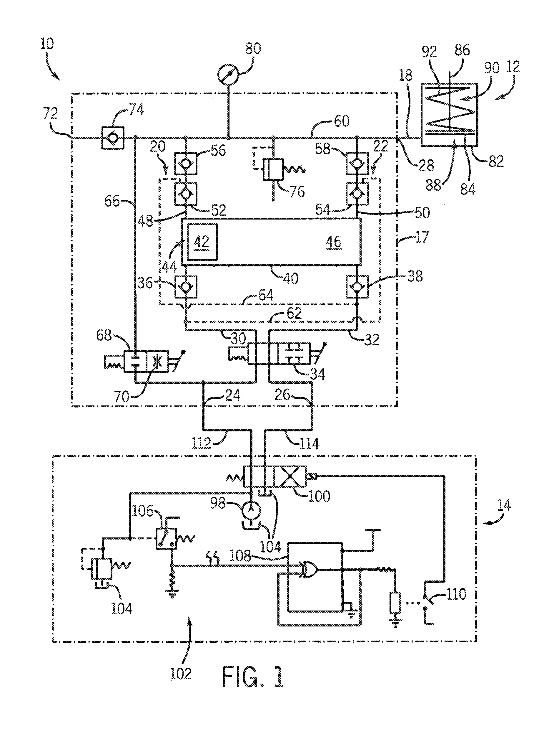
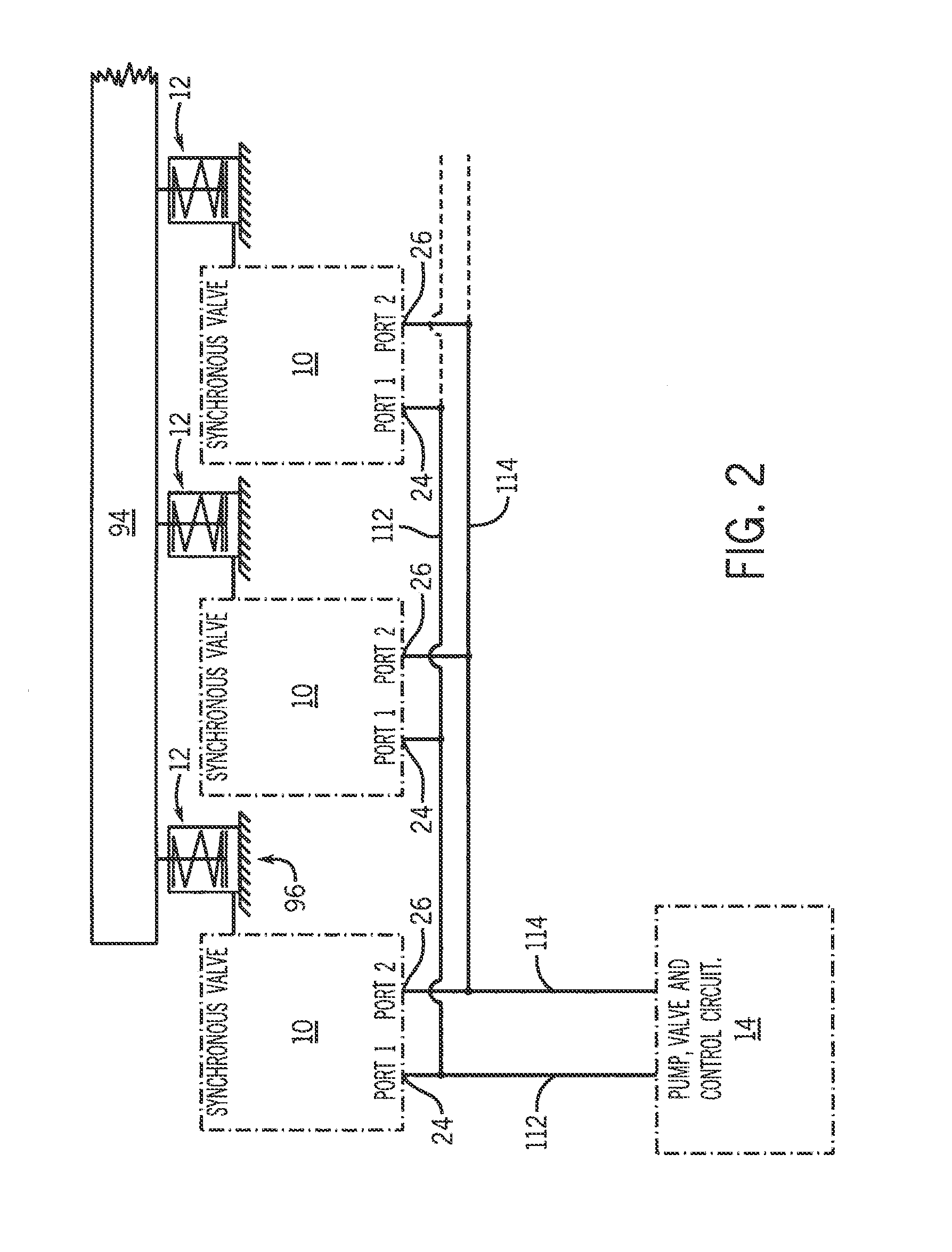
[0013]The present invention provides synchronized, incremental elevating (synchronized lifting and / or lowering) of a slab-like structure by a plurality of interconnected hydraulic actuators. The hydraulic and control circuits for a synchronous lift valve (sometimes referred to herein as an “elevating valve”, as “elevating” includes both lifting and lowering) and a synchronous lifting system are illustrated in the figures. As shown in FIG. 1, embodiments of a synchronous lift valve 10, single-acting lift cylinder 12, and fluid supply system 14 are schematically represented for a synchronized lifting system. FIG. 4 shows a system for synchronized lifting, like FIG. 1, but also for synchronized lowering.

[0014]Referring to FIG. 1, the lift valve 10 incrementally delivers a fixed volume of pressurized incompressible fluid, such as hydraulic fluid, to the lift cylinder 12 as further discussed below. As shown in FIG. 2, one embodiment of a synchronized lift system 16 includes a plurality o...


PUM


Abstract

A synchronous lifting or lowering system with hydraulic cylinders controlled by parallel-connected lift valves having two fluid passages. Hydraulic fluid for extending or retracting the actuators is delivered by a hydraulic supply system alternating between the two passages. Each time the supply circuit alternates passages, a fixed volume of hydraulic fluid is transferred during lifting or received during lowering by the respective lift or lowering valves to or from the cylinders causing the rods to lift or lower a proportionate amount. All of the rods extend during advancement or retract during lowering by approximately the same increment each time the supply circuit alternates passages. Because the rods all extend or retract the same increment each cycle, the load is lifted or lowered evenly and the need for height sensors or transducers is eliminated.

Description

CROSS-REFERENCE TO RELATED APPLICATION[0001]This application claims the benefit of U.S. Provisional Patent Application No. 61 / 757,485 filed Jan. 28, 2013, and is a continuation-in-part of International Patent Application No. PCT / US2012 / 032836 filed Apr. 10, 2012, which claims the benefit of U.S. Provisional Patent Application No. 61 / 477,931, filed Apr. 21, 2011, the disclosures of which are hereby incorporated by reference for all purposes.STATEMENT CONCERNING FEDERALLY SPONSORED RESEARCH OR DEVELOPMENT[0002]Not applicable.FIELD OF THE INVENTION[0003]This invention relates to the lifting or lowering of large structures such as slabs, foundations, bridges, buildings and other structures using a number of hydraulic actuators in a synchronized manner. As used herein, “lifting” includes pushing, hoisting, and all other applications in which hydraulic actuators are extended or retracted synchronously.BACKGROUND OF THE INVENTION[0004]Hydraulic systems for lifting structures such as slabs,...

Claims


Application Information

Patent Timeline
Patent Type & Authority Applications(United States)
IPC IPC(8): B66F3/46B66F3/24B66F7/20
CPCB66F3/46B66F3/24B66F7/20F15B11/12F15B11/22F15B2211/30505F15B2211/329F15B2211/405F15B2211/40515F15B2211/40576F15B2211/41527F15B2211/423F15B2211/71F15B2211/761F15B2211/782
Inventor STANFORD, FRANTZ D.
Owner ACTUANT CORP
Why Eureka
Try Eureka