Avalanche capability improvement in power semiconductor devices using three masks process

Active Publication Date: 2014-02-20
HSIEH FU YUAN +1
View PDF2 Cites 13 Cited by
  • Summary
  • Abstract
  • Description
  • Claims
  • Application Information

AI Technical Summary

Benefits of technology

[0008]The present invention has been conceived to solve the above-described problems with the related art, and it is an object of the invention to provide a technique which makes it possible to avoid the avalanche occurring nea

Problems solved by technology

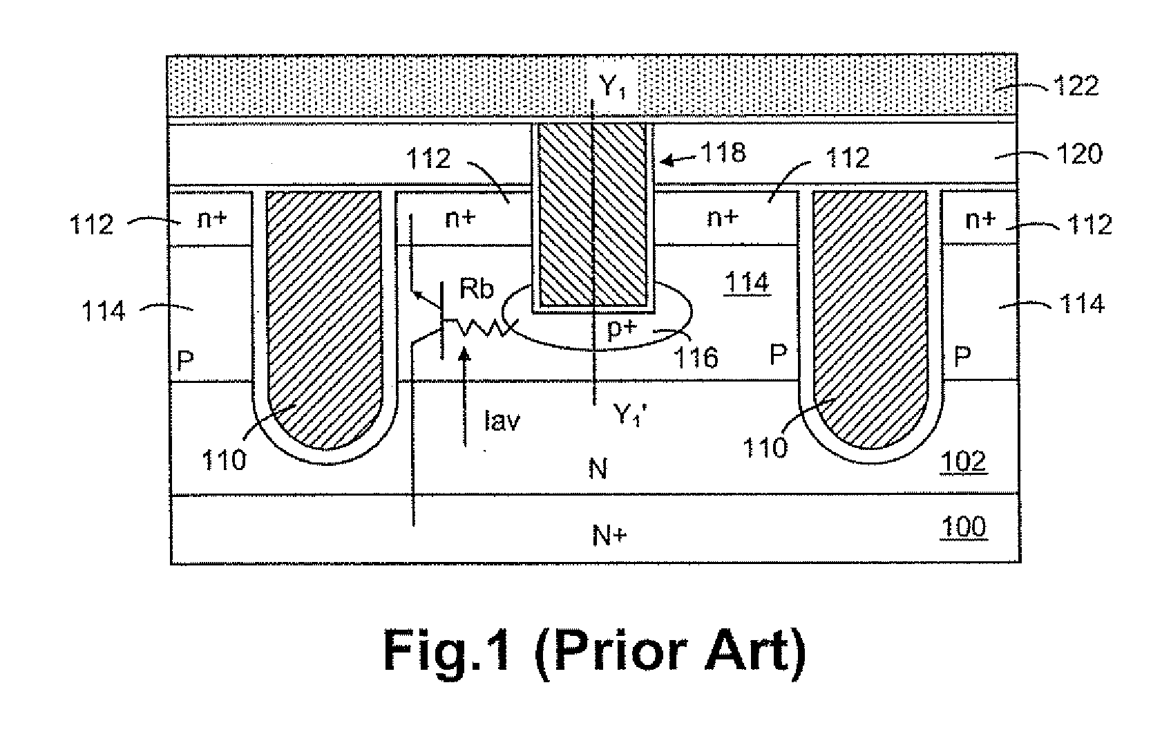
The conventional structure in FIG. 1 is accoutering a technical difficulty which is that avalanche always occurs near bottom of the trenched gates 110, causing a hazardous condition to the power semiconductor device.
Therefore, the parasitic bipolar transistor is easily to be triggered turning on due to the high resistance Rb, thus weakening the avalanche capability of the trench MOSFET.
However, the limitation of poor ava

Method used


Image

  • Avalanche capability improvement in power semiconductor devices using three masks process
  • Avalanche capability improvement in power semiconductor devices using three masks process
  • Avalanche capability improvement in power semiconductor devices using three masks process

Examples


Example

[0047]In the following Detailed Description, reference is made to the accompanying drawings, which forms a part thereof, and in which is shown by way of illustration specific embodiments in which the invention may be practiced. In this regard, directional terminology, such as “top”, “bottom”, “front”, “back”, etc., is used with reference to the orientation of the Figure(s) being described. Because components of embodiments can be positioned in a number of different orientations, the directional terminology is used for purpose of illustration and is in no way limiting. It is to be understood that other embodiments may be utilized and structural or logical changes may be make without departing from the scope of the present invention. The following detailed description, therefore, is not to be taken in a limiting sense, and the scope of the present invention is defined by the appended claims. It is to be understood that the features of the various exemplary embodiments described herein...


PUM


Abstract

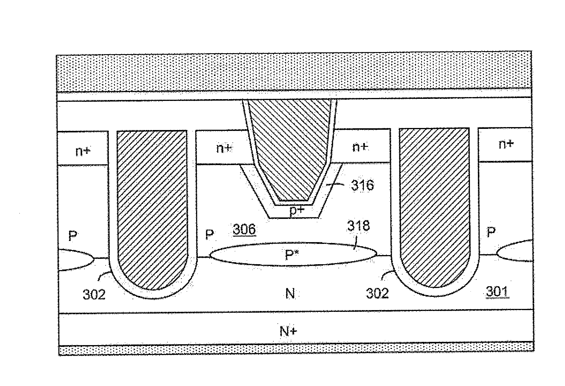
A power semiconductor device with improved avalanche capability is disclosed by forming at least one avalanche capability enhancement doped region underneath an ohmic contact doped region. Moreover, a source mask is saved by using three masks process and the avalanche capability is further improved.

Description

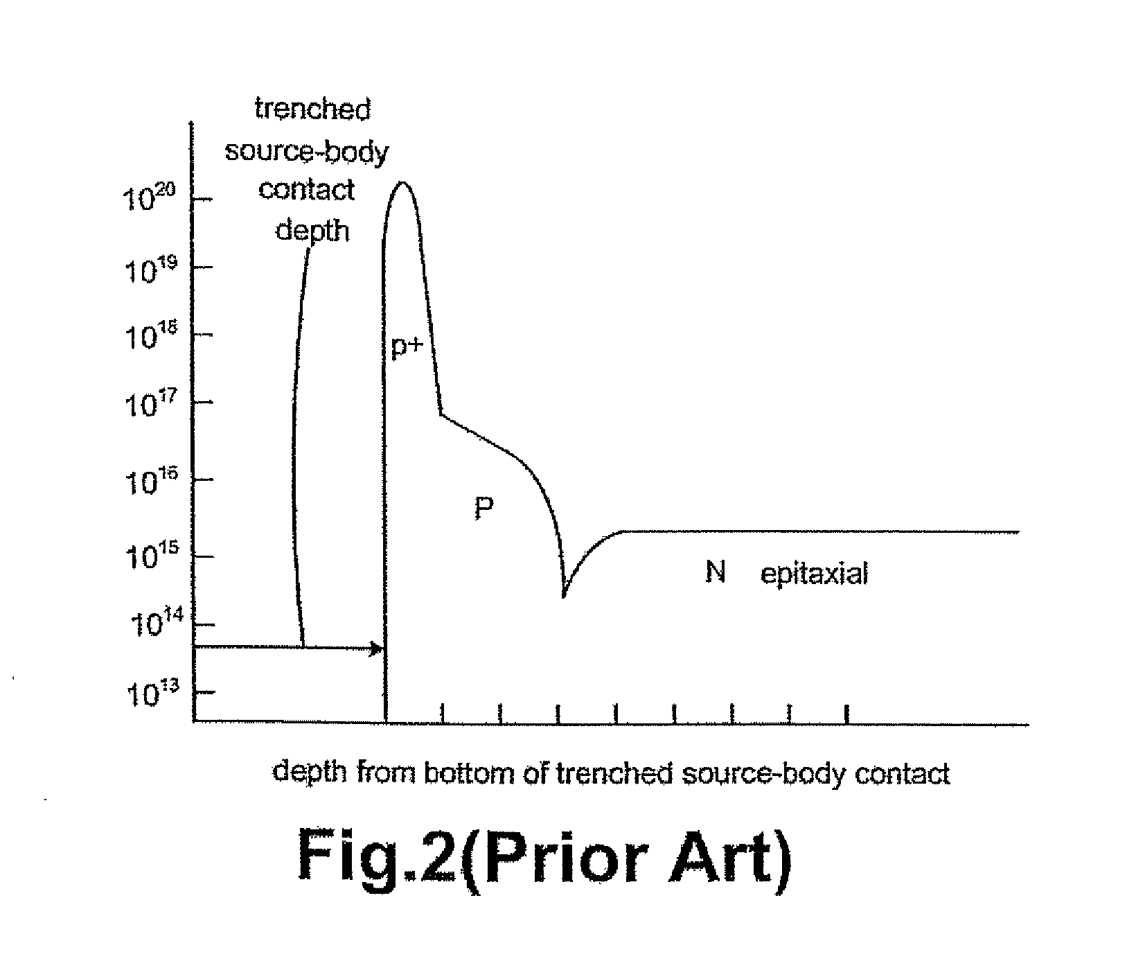
CROSS REFERENCE TO RELATED APPLICATIONS[0001]This application is a Continuation-In-Part (CIP) of U.S. patent application Ser. No. 13 / 585,059 of the same inventor, filed on Aug. 14, 2012, entitled “method for manufacturing a power semiconductor device”.FIELD OF THE INVENTION[0002]This invention related generally to the cell structure and device configuration of power semiconductor devices. More particularly, this invention relates to power semiconductor devices with improved avalanche capability.BACKGROUND OF THE INVENTION[0003]In U.S. Pat. No. 6,888,196, a conventional structure of power semiconductor device is disclosed, as shown in FIG. 1, wherein an N-channel trench MOSFET comprising a plurality of trenched gates 110 surrounded by n+ source regions 112 encompassed in P body regions 114 is formed in an N epitaxial layer 102 over an N+ substrate 100. To connect the source regions 112 and the body regions 114 to a source metal 122, a trenched source-body contact structure 118 with v...

Claims


Application Information

Patent Timeline
IPC IPC(8): H01L29/78H01L29/66
CPCH01L29/66666H01L29/7827H01L29/0626H01L29/1095H01L29/41766H01L29/4236H01L29/456H01L29/66727H01L29/66734H01L29/7397H01L29/7808H01L29/7813
Inventor HSIEH, FU-YUAN
Owner HSIEH FU YUAN
Why Eureka
Try Eureka