Intershaft seal

a technology for intershaft seals and sealing rings, applied in the direction of engine seals, mechanical equipment, engine components, etc., can solve the problems of heat generation and wear, contact forces between the runner and the sealing ring,

Active Publication Date: 2014-02-20
ROLLS ROYCE PLC
View PDF18 Cites 6 Cited by
  • Summary
  • Abstract
  • Description
  • Claims
  • Application Information

AI Technical Summary

Benefits of technology

[0012]wherein the sealing ring has a main body portion formed of a first material having a first stiffness, and further has a retaining ring fitted to the radially outward side of the body portion and formed of a second material having a second stiffness, the second stiffness being greater than the first stiffness such that the retaining ring reduces or prevents radial growth of the sealing ring relative to the outer shaft under centrifugal loading.
[0013]Due to the higher stiffness of the retaining ring, the radial growth of the sealing ring can be substantially reduced under centrifugal loading, even to the point where the radial growth of the sealing ring is matched to that of the outer shaft such that no relative radial growth occurs. This allows interference or clearance between the sealing ring and the outer shaft to be better controlled such that any centrifugal loading dependence of the frictional force between these components can be reduced or eliminated. Resistance to axial sliding of the sealing ring relative to the outer shaft can thus be controlled. In the case of an air-riding seal arrangement, the air film can thus overcome any frictional force to prevent contact at the annular sealing interface. In the case of a contacting seal arrangement, contact forces between the runner and the sealing ring can be limited to reduce heat generation and wear.
[0019]Due to the higher CTE of the retaining ring the radial contraction of the sealing ring can be substantially increased. This can be particularly beneficial on cold starts when the seal temperature may be substantially lower than the temperature (typically room temperature) at which the sealing ring is fitted to the shafts. In this way, interference or clearance between the sealing ring and the outer shaft can be better controlled. More generally, as the CTE of the shafts is typically higher than the CTE of the main body portion of the sealing ring, having a relatively high CTE for the retaining ring can help to better match the overall CTE of the sealing ring to the CTE of the shafts.
[0029]The retaining ring may be formed of metal or fibre reinforced composite material. Composite material, such carbon fibre reinforced plastic, can reduce the weight of the component but may be restricted to use in relatively low temperature applications.
[0031]The sealing ring may further include one or more secondary seals which seal between the sealing ring and the outer shaft. The secondary seals can be particularly beneficial when there is a clearance between the sealing ring and the outer shaft. A secondary seal can be carried by the sealing ring, e.g. by the retaining ring, or a secondary seal can be carried by the outer shaft. Another option is for a secondary seal to be an annular bellows formation having ends which are fixed to respectively the sealing ring and the outer shaft. Such a bellows formation can also function as an anti-rotation device which prevents rotation of the sealing ring relative to the outer shaft but allows limited axial movement of the sealing ring relative to the outer shaft.

Problems solved by technology

In the case of a contacting seal arrangement, contact forces between the runner and the sealing ring can be limited to reduce heat generation and wear.

Method used


Image

  • Intershaft seal
  • Intershaft seal
  • Intershaft seal

Examples


Embodiment Construction

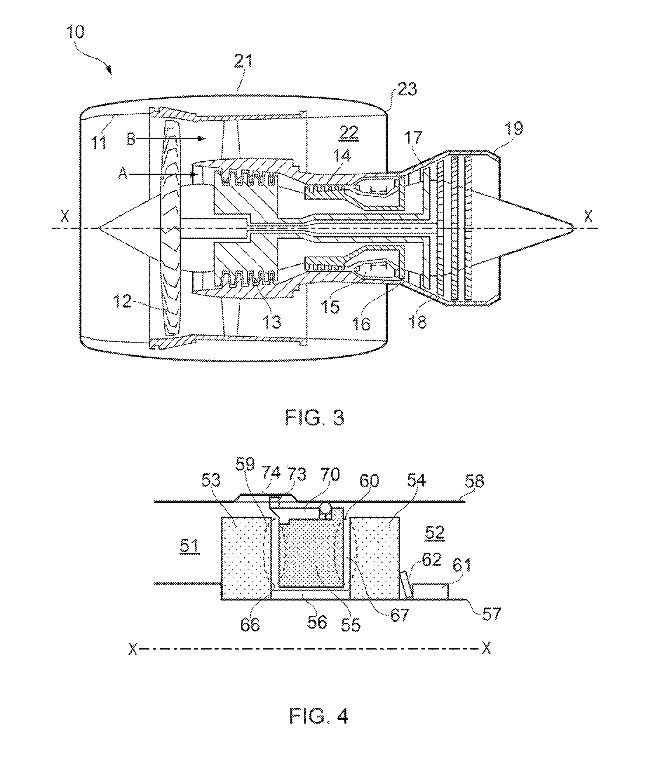
[0045]With reference to FIG. 3, a ducted fan gas turbine engine incorporating the invention is generally indicated at 10 and has a principal and rotational axis X-X. The engine comprises, in axial flow series, an air intake 11, a propulsive fan 12, an intermediate pressure compressor 13, a high-pressure compressor 14, combustion equipment 15, a high-pressure turbine 16, and intermediate pressure turbine 17, a low-pressure turbine 18 and a core engine exhaust nozzle 19. A nacelle 21 generally surrounds the engine 10 and defines the intake 11, a bypass duct 22 and a bypass exhaust nozzle 23.

[0046]During operation, air entering the intake 11 is accelerated by the fan 12 to produce two air flows: a first air flow A into the intermediate pressure compressor 13 and a second air flow B which passes through the bypass duct 22 to provide propulsive thrust. The intermediate pressure compressor 13 compresses the air flow A directed into it before delivering that air to the high pressure compre...


PUM


Abstract

An intershaft seal is provided for inner and outer coaxial shafts which rotate relative to each other. The seal is located in an annular space between the shafts and maintains an axial pressure differential between a fluid pressure on the first side of the seal and a different fluid pressure on the other, second side of the seal. The seal includes a first runner which extends circumferentially around a first one of the shafts and projects therefrom into the annular space. The seal further includes a sealing ring which is coaxial with the shafts.

Description

FIELD OF THE INVENTION[0001]The present invention relates to an intershaft seal.BACKGROUND OF THE INVENTION[0002]Numerous types of intershaft seal can be used to seal between relatively rotating coaxial shafts as found e.g. in gas turbine engines. One type of intershaft seal is shown schematically in FIG. 1 and is used to seal between gas, liquid or air-gas mixtures. The seal is located between inner 37 and outer 38 coaxial shafts and maintains an axial pressure differential between high pressure fluid 31 on a first side of the seal and low pressure fluid 32 on a second side of the seal. The shafts rotate relative to each other. The seal comprises a carbon ring 35 positioned between first 33 and second 34 runners on respectively the first and second sides of the seal. The carbon ring typically has a slight clearance from the outer shaft at cold build conditions. The two runners are separated by a spacer 36, so that the axial gap between the runners is slightly longer than the axial ...

Claims


Application Information

Patent Timeline
Patent Type & Authority Applications(United States)
IPC IPC(8): F16J15/30F16J15/26
CPCF16J15/26F16J15/30F16J15/3452F16J15/3464F16J15/441
Inventor JAHN, INGO HENRY JOHANNESDAVIES, CHRISTOPHER
Owner ROLLS ROYCE PLC
Why Eureka
Try Eureka