Vehicle door handle device

a technology for a vehicle and a handle, which is applied in the direction of locking applications, mechanical devices, fastening means, etc., can solve the problems of increasing the number of components, the structure of the forming mold becomes extremely complex, and the collision noise of the operation handle is reduced, and the configuration is simple.

Active Publication Date: 2014-02-20
ALPHA +1
View PDF0 Cites 22 Cited by
  • Summary
  • Abstract
  • Description
  • Claims
  • Application Information

AI Technical Summary

Benefits of technology

[0005]The embodiment of the present invention relates to a door handle device for a vehicle, which is capable of reducing the collision noise of an operation handle at the time of returning with a simple configuration.

Problems solved by technology

However, in this device, an undercut to a drawing direction of a mold is configured due to the connecting plate portion for connecting the leading ends of the guide walls that are long in a moving direction of the guide arm.
Therefore, there is a problem that the structure of a forming mold becomes extremely complex.
Furthermore, a separate cushion is required and therefore an increase in the number of components and an increase in the process number of component mounting working are caused.

Method used


Image

  • Vehicle door handle device
  • Vehicle door handle device
  • Vehicle door handle device

Examples


Embodiment Construction

[0012]Hereinafter, the embodiments will be described with reference to the drawings. Here, the embodiments are illustrative of the present invention and not intended to limit the present invention. It should be noted that all the features and their combinations described in the illustrative embodiments are not necessarily considered as an essential part of the present invention.

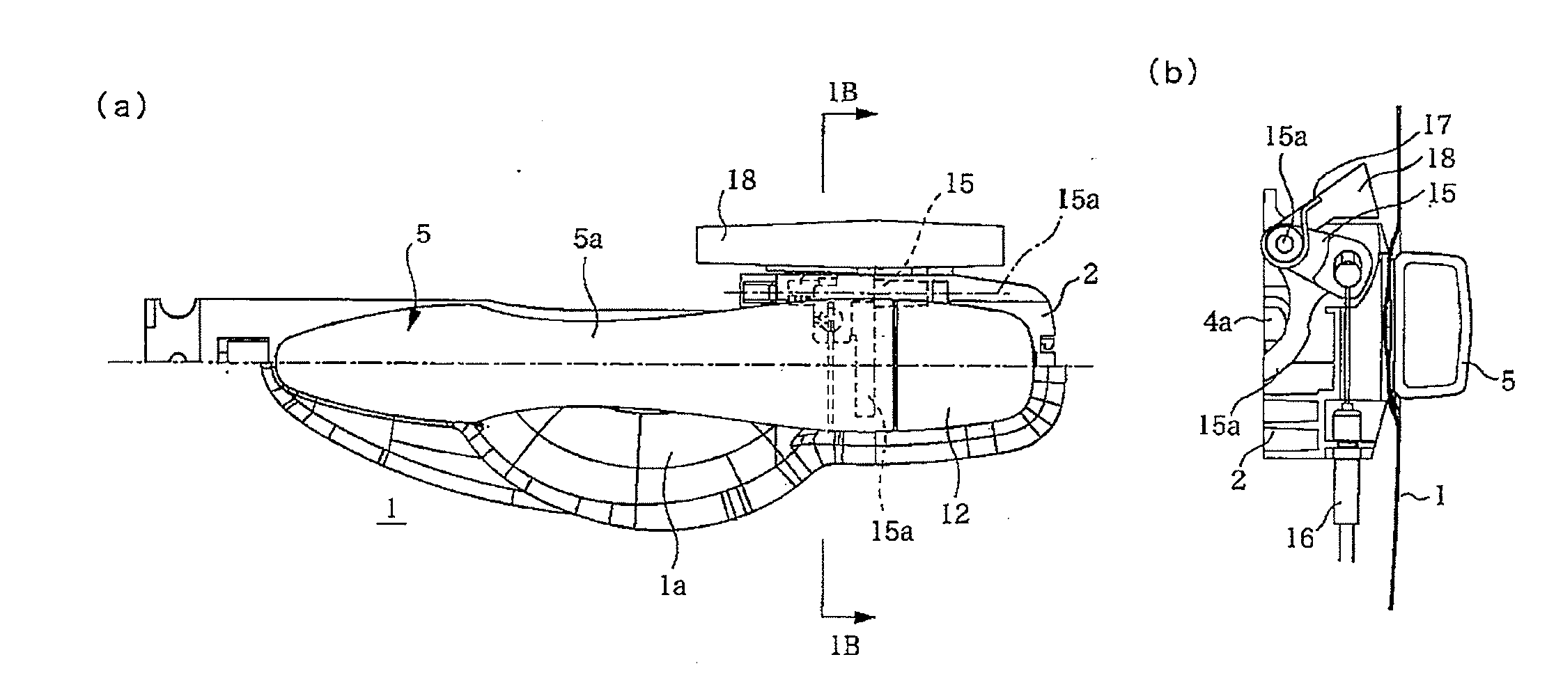
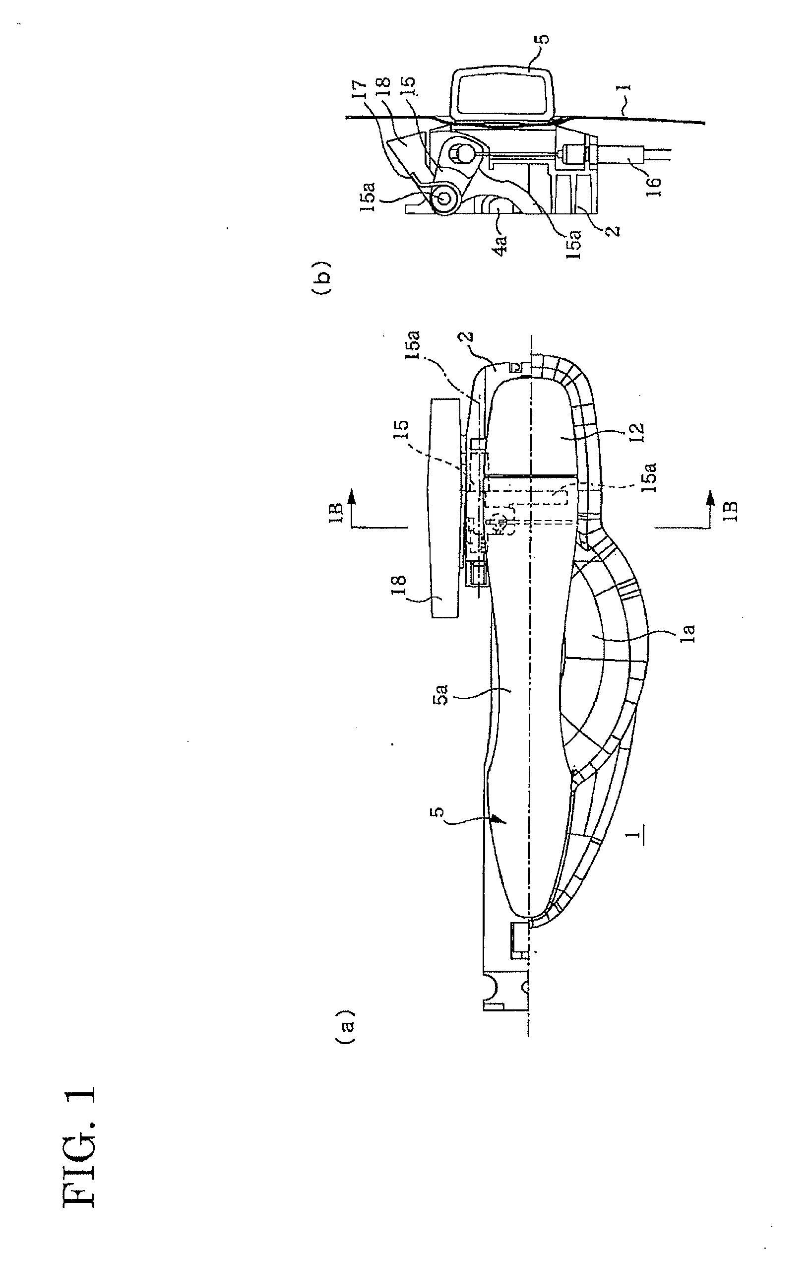
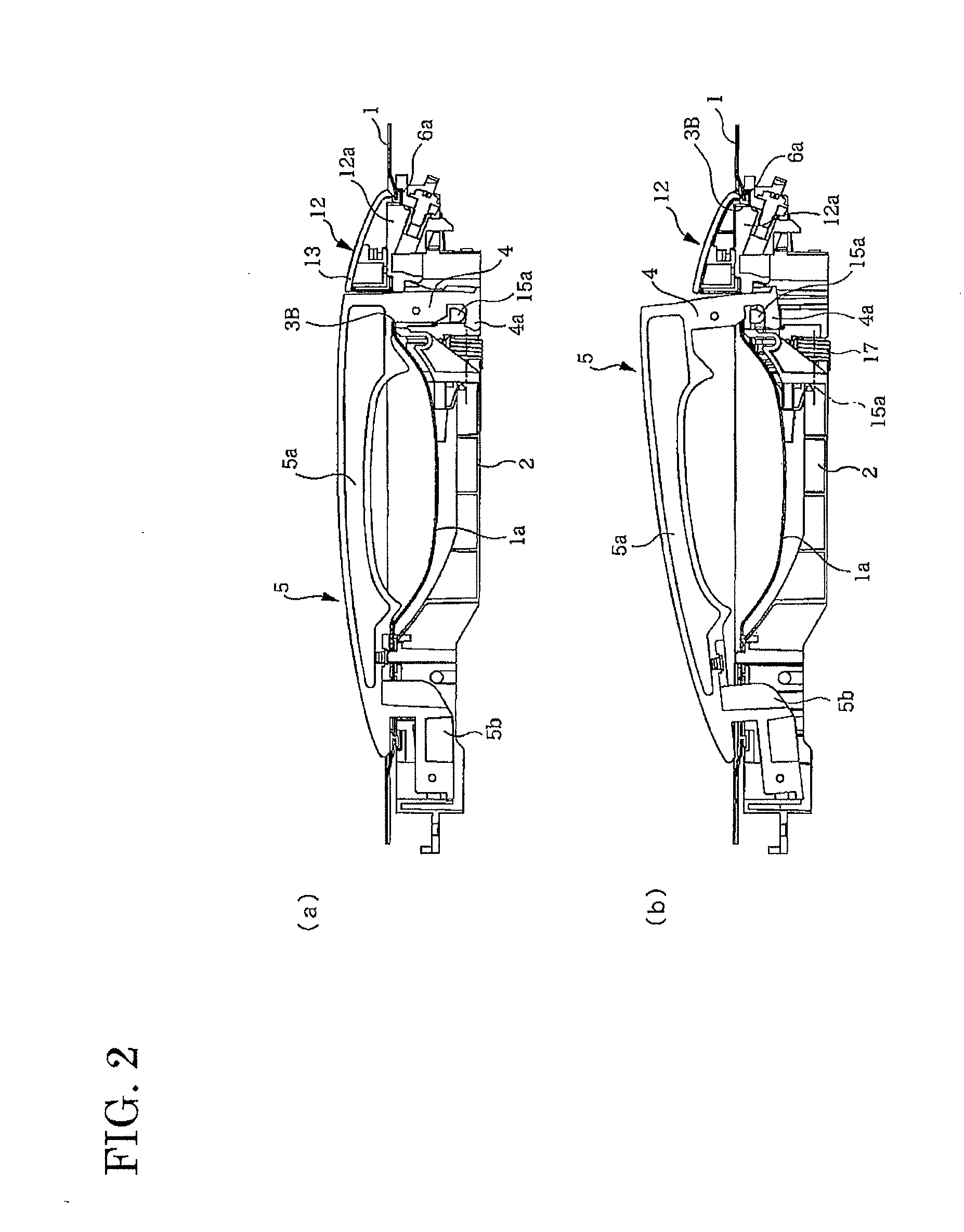
[0013]As shown in FIG. 1 to FIG. 3, a door handle device of a vehicle is formed in such a way that an operation handle 5 is rotatably connected to one end of a handle base 2 disposed along a bottom surface of a door panel 1. In this embodiment, the handle device is mounted in a posture where a left side thereof in section (a) of FIG. 1 is directed toward the front of a vehicle. Hereinafter, in the present specification, with reference to a mounting posture to a vehicle, a longitudinal direction of a vehicle is referred to as “a front and rear” and a width direction of a vehicle is referred to as “a top and bo...


PUM


Abstract

This door handle device is provided with: a handle base; an introduction opening that is opened in a door handle and that supports the handle base; an operation handle that is connected to the handle base; and a gasket that is disposed between the handle base and the operation handle. A handle stopper, of which one end passes through the introduction aperture and is borne by the handle base, and of which the other end contacts the operation handle, is integrally provided to the gasket.

Description

TECHNICAL FIELD[0001]The present invention relates to a door handle device for a vehicle.BACKGROUND ART[0002]Patent Document 1 discloses a handle device for preventing the occurrence of collision noise when returning to an initial rotational position. In the device disclosed in Patent Document 1, a guide arm is projected in a handle (operation handle) connected to a base member (handle base) and moves between guide walls of the handle base. A cushion member is fixed to a connecting plate portion connecting the lower ends of the guide walls. The cushion member prevents the occurrence of the collision noise by abutting against a lower end of the guide arm when the operation handle is returned to the initial rotational position.[0003]However, in this device, an undercut to a drawing direction of a mold is configured due to the connecting plate portion for connecting the leading ends of the guide walls that are long in a moving direction of the guide arm. Therefore, there is a problem t...

Claims


Application Information

Patent Timeline
Patent Type & Authority Applications(United States)
IPC IPC(8): E05B65/12
CPCE05B85/14E05B79/06E05B85/16E05B77/38Y10T292/57
Inventor KUDOH, SHUICHIICHIKAWA, SHINJIYOSHIDA, RYUICHITSUJI, KOUJI
Owner ALPHA
Why Eureka
Try Eureka